The older style HVAC thermostat while programable was a P.I.T.A. requiring a learning curve with flashlight and small printed diagram each time. So, I bought a cloud connected unit that promised easy scheduling and operation along with simple DIY and compatibility. All very fine until installation time that required a fifth wire between wall mounted device in the hallway and furnace upstairs. 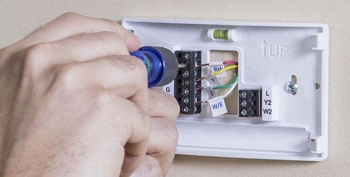 While it was trivial to connect the existing coded 4 wires I was able to sleuth an explanation online for better understanding of the meaning of the codes and how the system operates. This would prove useful.
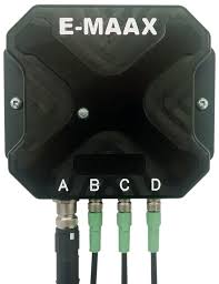
For Reference:
- W – Heating (white wire)
- R – Continuous 24 v ac Power (red wire)
- G – Fan (green wire)
- Y – Cooling (this wire is yellow in the diagram)
- C – Common (this wire is blue in the diagram)
Closing R and W will initialize the heating cycle. The blower operates independently as determined by a separate furnace heat exchanger mounted temperature controller. In other words, once the heating chamber is properly warmed up the blower will come on. Similarly, when the thermostat shuts the gas valve, the blower continues to run until the furnace has cooled. Closing R and G will initialize the blower (FAN only) Closing R and Y will initialize the cooling cycle AND the blower.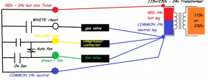 The schematic shows a diode (one-way) between Fan and Cooling function so that operating the Fan in manual mode doesn’t run the AC but running the AC will run the [blower] Fan.
 The schematic shows a diode (one-way) between Fan and Cooling function so that operating the Fan in manual mode doesn’t run the AC but running the AC will run the [blower] Fan.
That blue wire coded “C” in the diagram is the 5th wire mentioned for the installation. It is not used in my old tech thermostat but required to power the WiFi in the new one. Fortunately it was available as part of the existing cable bundle at the wall mounting point and quick to attach to the new thermostat.
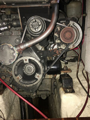
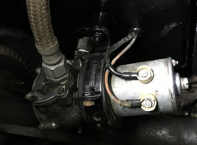
Not so fast was connecting the other loose end of that wire in the furnace room. The example furnace in the instructional video was modern and straightforward with printed circuit board and nicely labeled terminals. Mine looked very different and I was faced with this:
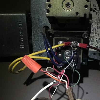
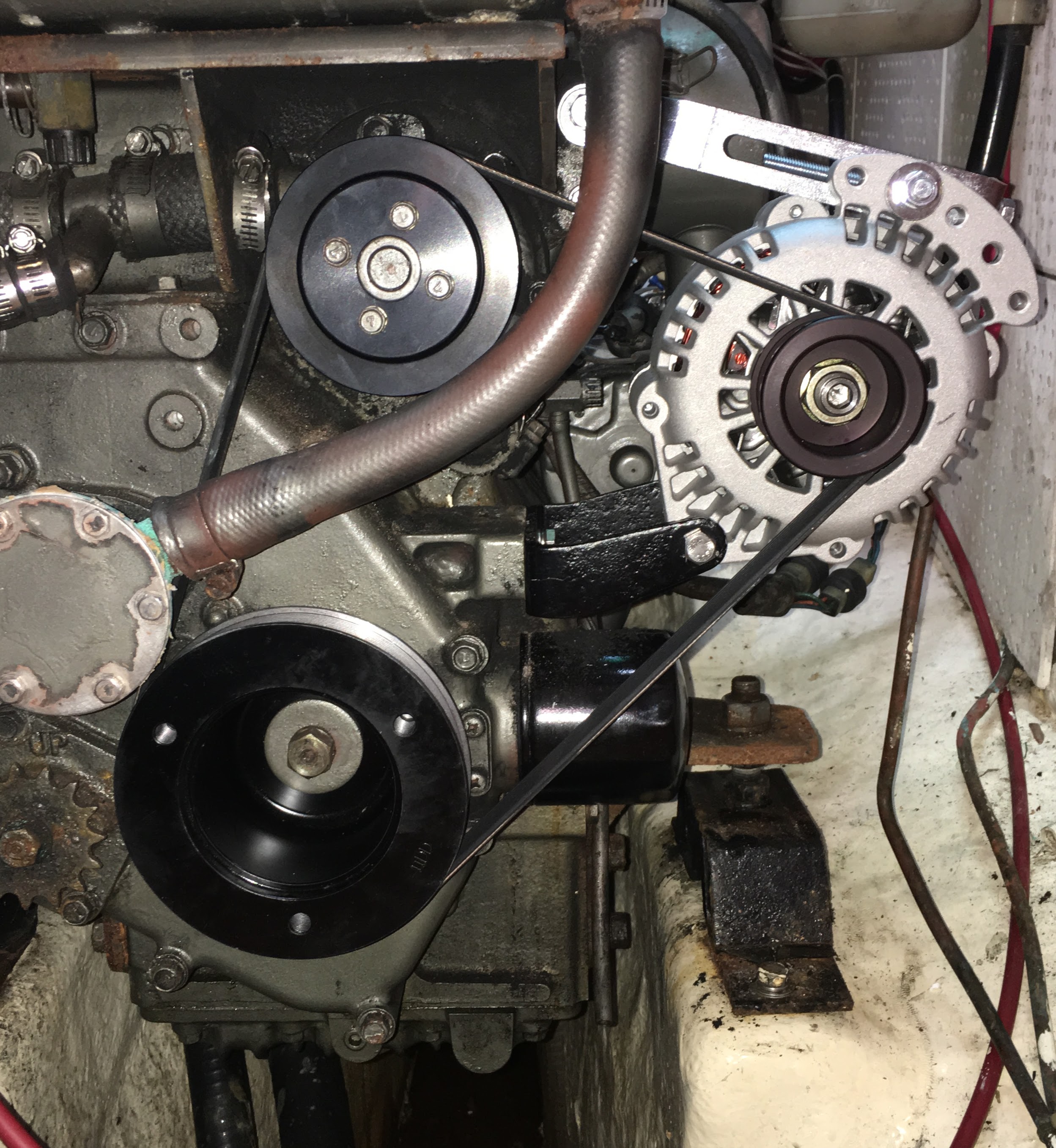
I believe the term is Spaghetti. No worries. Just tracing the wire color back to the thermostat gave understanding of the terminal to which it was connected. Finding the “C” terminal was a process of elimination but to be certain I applied the probes of my pocket multimeter and looked for voltage and/or the absence thereof. I hit a roadblock when the meter showed excessively high readings (60v) and on every terminal?! I was sure I was looking at a defective transformer. I spent an embarrassing length of time Googling a replacement part in between back and forths for Voltage checks and rechecks. Something was amiss. It was a classic Red herring until I saw the error of my ways. The multimeter setting defaulted to DC and I erroneously believed that was the output I was looking for. The transformer drops the 115v AC to 24v but doesn’t convert it. i.e. the Current was still AC. 24v AC. I changed the function switch from DC to AC and suddenly everything was all good!
I completed the installation and buttoned things up. Works perfectly and I can program intuitive heating and cooling schedules to heart’s content – instruction manual not required.
 v1.5
v1.5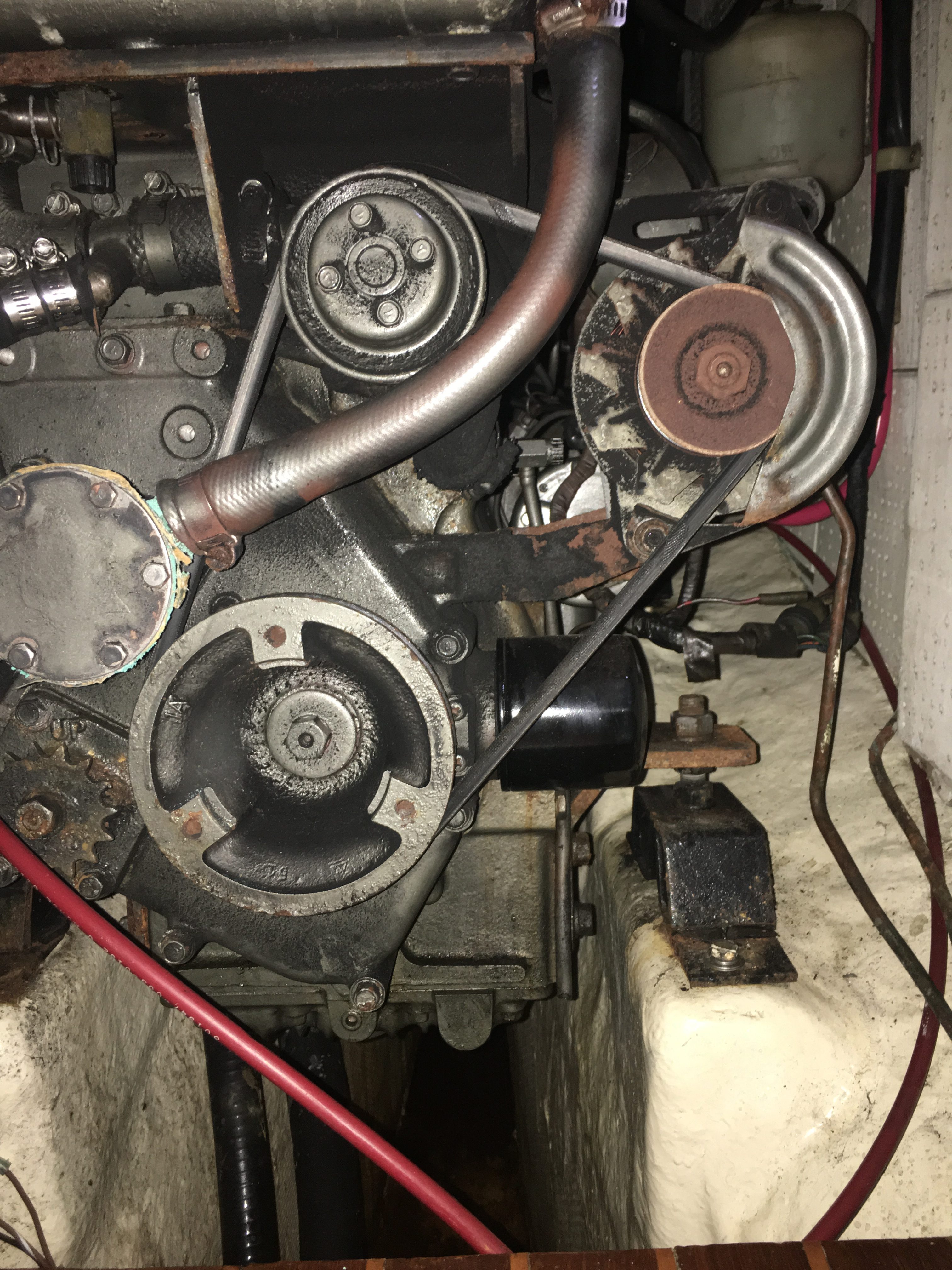