Customer complains that when the unit is not running a musty smell permeates the area in the vicinity of the main return air vent. The odor is strong from behind the vent filter. With the blower fan in start up, a good sneeze is a common coincidence.
The AC evaporator coil is deep within the unit and is the likely source. Continuous moisture from normal condensation drips down onto the shallow floor of the coil box compartment where it drains away by gravity. Check here first to be sure that this drain isn’t blocked. Remove the access panel for a look see.
In this situation that precursory peak revealed nothing out of the ordinary. Residual amount of collected condensate was very clean and the coil, unremarkable externally.
The other side, top, and bottom of the evaporator box is sealed and access from the ends blocked by the blower [box] unit and plenum [box] chamber.
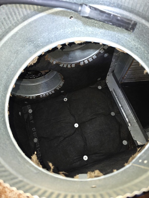
Removing one of the [plenum] return air ducts reveals an inside look. At the top are two more return air duct ports. The box is lined with sound absorbing insulation. To the right of the image is a glimpse of the lower corner of one side of the evaporator.
This temporary access portal is just large enough to stick hand/arm into.
I angled a camera just so for the money to find a smoking gun.
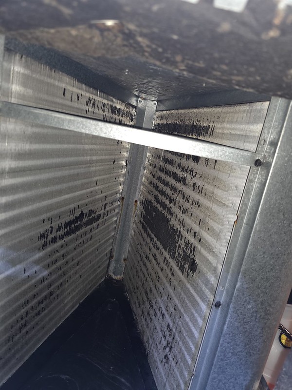
The black junk found adhering can’t be good.
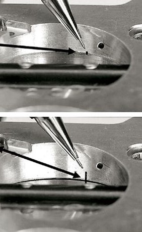
The coil is a heat exchanger with delicate aluminum fins doing the transfer. A combination of cleansing solution and brush work will remove the crud but care is needed. Brush strokes must be vertical (in the direction of the fins) as any lateral force will bend and deform them. If carried to the extreme they will lay down against the adjacent ones blocking their narrow air passages shut.
Note the far end. That is not an error of perspective. The two coil slabs are “V” shaped so space becomes confined and you mustn’t do damage with that brush motion.
Most people select from commercially available concentrate cleaner or you might make your own using readily available household items.
2 parts vinegar, 1 part water, 4 table spoons of liquid detergent (e.g. Dawn) for some foaming cling. Optional: a dollop of hydrogen peroxide (3% solution) to enhances antimicrobial action. Be cautious about brewing up anything toxic. For example, vinegar mixed with bleach = chlorine gas. Skull and Crossbones.
Use a pressure pump bottle with wand to spray. Let sit for 10 minutes. Brush gently. Repeat. Give that padding mat in the plenum a coating as well. Use a wet vac over the pad to remove excess. Run the HVAC (or fan only mode) to assist in the drying.
The heavy mold stuff is 20 years of neglect but hopefully the chemical will kill it. Now for the sniff test.