The electrical system onboard Talmid, while well executed and adequate by OEM standards, could benefit from a re-fit. Modern comfort necessities and new equipment rely on a robust electrical system not foreseen back in the day. Battery chemistry has improved but that comes with stricter charging care and feeding requirements. There are improved energy source options in both solar and wind.
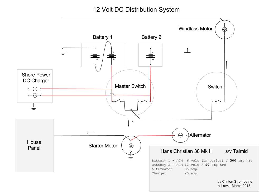
Follows is a schematic and narrative for what I have in mind for the boat. Central is the Battery system which is comprised of the House Bank (Battery #1) and an Engine Starting Battery (#2).
The original system is wholly dependent on the engine driven alternator to restore a discharged House Bank. Proper seamanship dictates that the Starting Battery always be reserved for engine starts for which this need should be obvious. Switching allows the selection of Engine Battery or House Battery or Both (together in parallel) or OFF. This is good flexibility but when you crank the starter motor there is huge voltage sag. This results in lights dimming, the GPS signal being lost, and the Navigation Course Plotter resets. Sometimes it kicks off the Auto Steering too. Surges and spikes aren’t good for electronics. This happens because all consumers are tied to the same battery. The switching can only direct to the source.
This new design above allows for three battery switch choices: ON, OFF, and Manual Combine. Combine (aka Both) is for an unusual situation only (e.g. a battery bank has gone flat) and the normal operational selection is: ON. Each battery system is split. 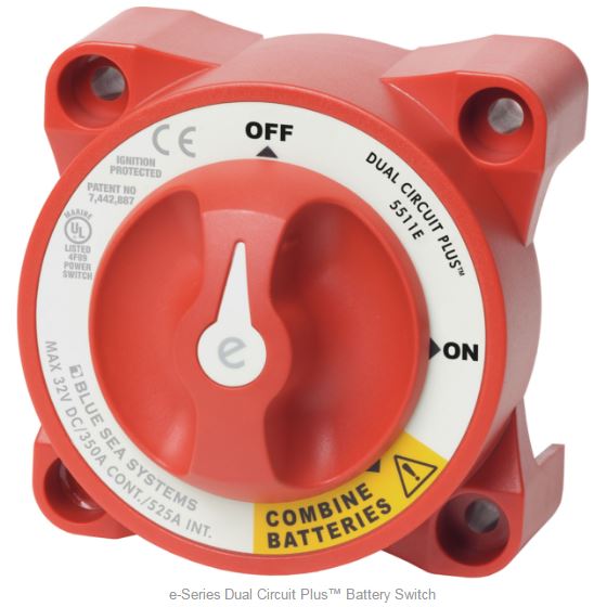 Thus, if the engine is started, the other consumers can continue to chug away without interference. Split batteries are good practice because if there is a heavy discharge, or a short circuit or failure loss on one battery side then the other battery side is not likely to be affected.
This new design will require battery charging leads to one battery system or the other in order to maintain the desired isolation. However, there is a way to maintain a proper charge 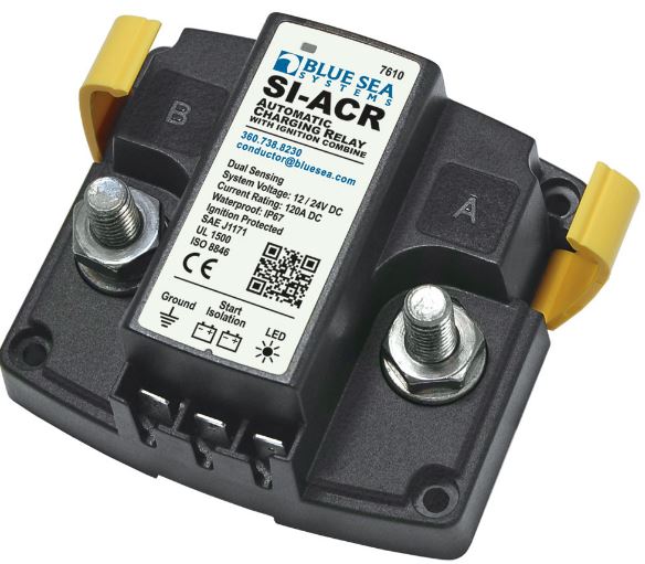 state on both battery banks through the use of an Automatic Charging Relay (ACR). This hardware, through a one way only (diode protected) connection permits charge voltage to pass to both batteries. When the ACR senses discharge the connection between the two banks is opened. The schedule is programed to work with system voltage as follows when:
- Voltage > 13.6v combine after 30sec.
- Voltage > 13.0v combine after 90 sec.
- Voltage < 12.75v open after 30 sec.
- Voltage < 12.35v open after 10 sec.
There is some overhead for the ACR. It has a small energy draw. Also, there is a fallibility with voltage sensing relays to do with combining and isolation cycling. To mitigate the possibility, the charge energy sources are defaulted to the (house) battery bank that is likely to experience the most discharge. Further, when adding complexity to a system you have to assume it to be a point of failure.