Tag Archives: DIY

Do It Yourself

Never the Right Tool #*!!

A statement of frustration blurted by my Father when attempting a household repair. I think his meager tool box consisted of pliers, crescent wrench, hammer,  pipe wrench and a couple of screwdrivers and bailing wire; so, when the odd DIY task such as connecting the new dishwasher came along his kit was lacking. The lament always signaled impending defeat and preceded the interruptive trip to the hardware store.


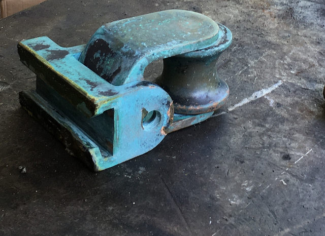
Flash forward. I have a rather massive 14mm Allen Wrench used to remove the hex pattern oil fill/drain plugs on my vintage car.  This tool allows me to service fluid level on both the transmission and differential. Almost. It turns out that this trusty wrench is too bulky to access the fill plug on the rear axle.  baulky allen key
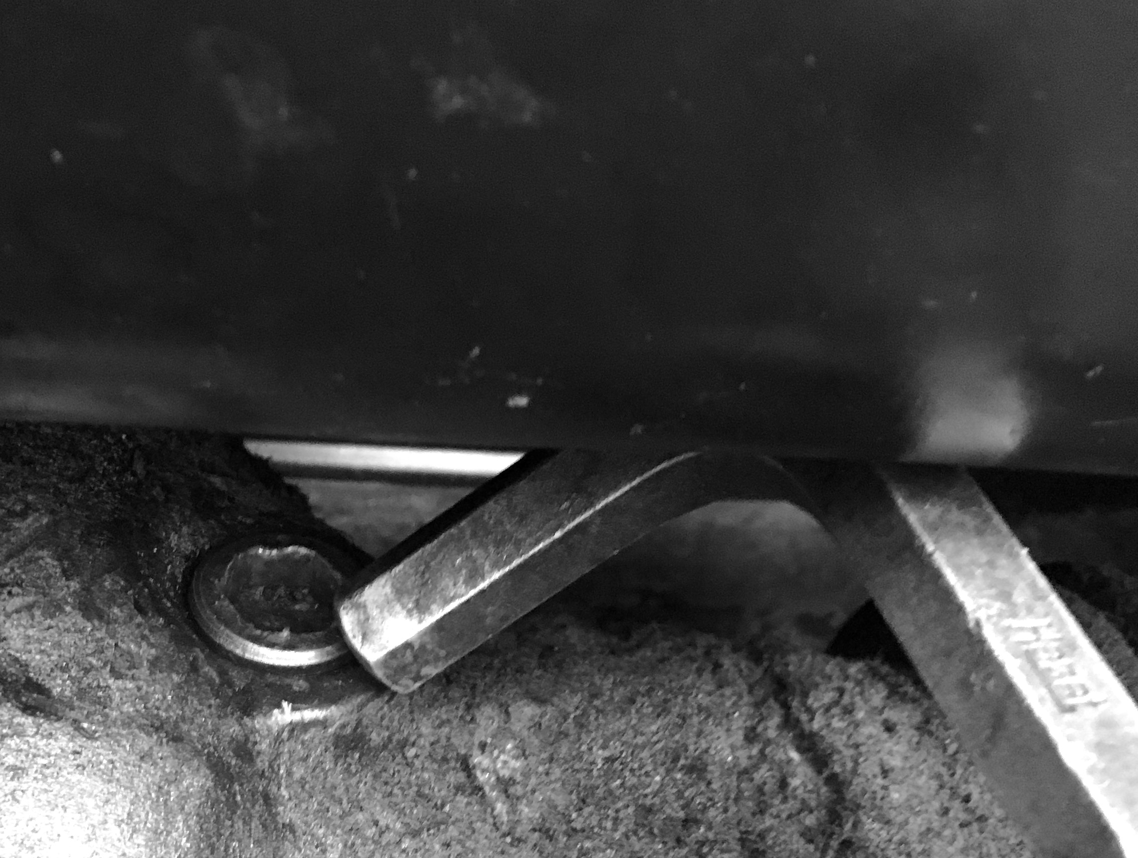
The tool won’t physically fit between the plug and the adjacent gas tank. Consternation follows. What was the method to pull this plug? What tool did I use before and where is it now? Had I ever actually serviced this item? My rolling chest of drawers, while hardly complete, is still a far cry from the random assortment in my Dad’s day. Still, after rummaging through, I realized that I didn’t own the proper tool; a short straight hex key on a 3/8″ socket.

Instead of halting the operation, getting cleaned up, and driving to the Auto Parts House (the proper thing) but in grand gesture toward Dad’s way — I improvised.

Staring thoughtfully at the internal hex pattern in the plug it occurred to me that a hex head bolt (male) might just be the ticket.tight fit 
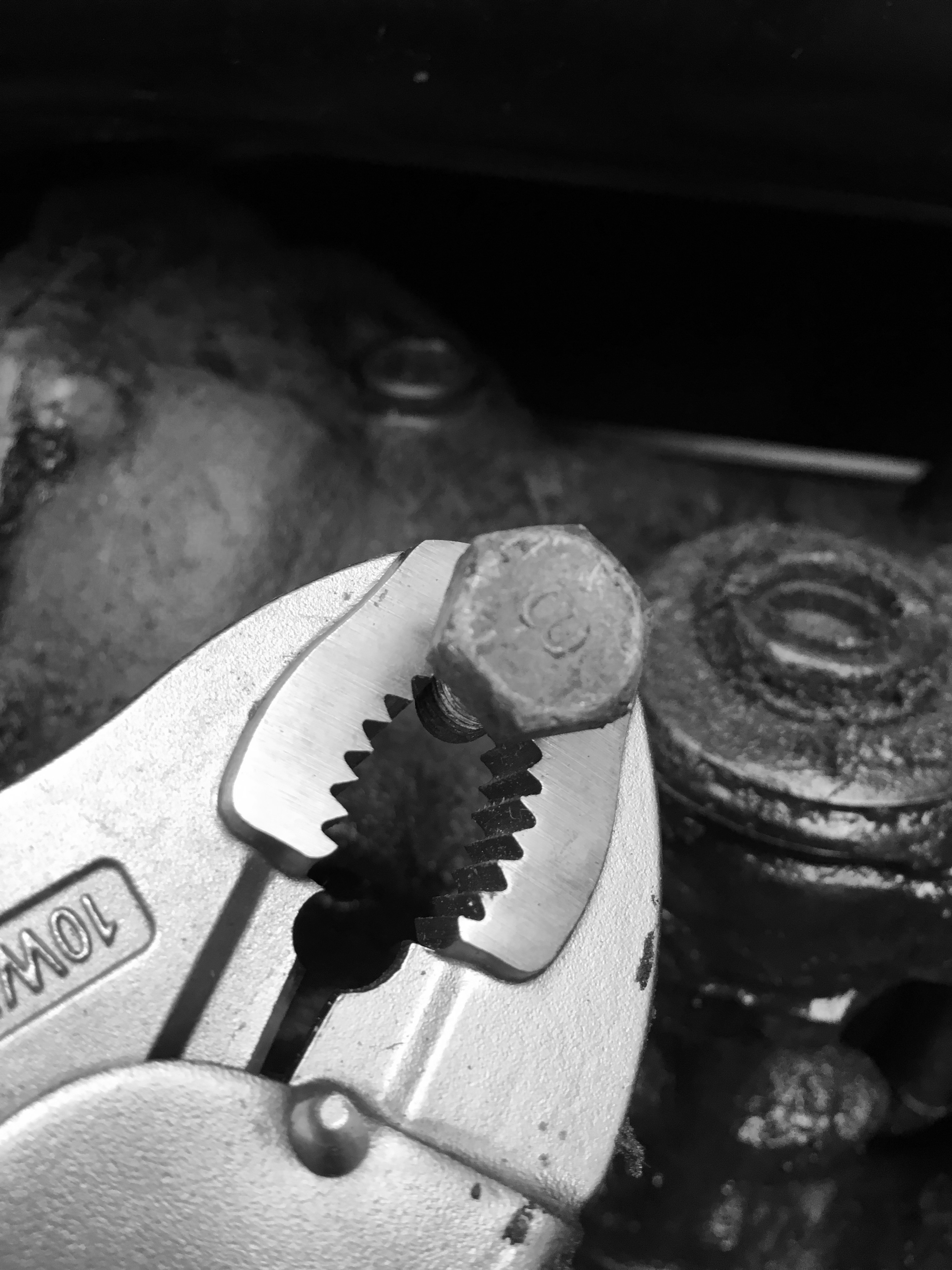
14mm is nearly equivalent to .5″ and my salvaged supply of old bolts might offer a match. I eyeballed a handful of candidates and then began to measure in a more precise way with Calipers.  A lag bolt with head measuring .56″ was too great a span, another sample, inadequate. I didn’t want to louse up the female end of the plug. A bolt head that was too small would surely strip it.

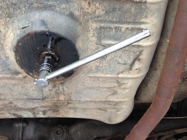
An old carriage bolt turned up as suitable and with vice-grips pliers for leverage I was able to cleanly extract the unmanageable plug.

Exasperation avoided and a run to the store annoyance averted, when next surfing Amazon I will order: “The Right Tool”

leave less to chance

What can go wrong WILL go wrong. sorry keyI only had the one key and it was really looking past it. Not visible by thumbnail image is a hairline crack across the blade; a victim of too many bendings from body bumps and slams (the engine control panel and ignition switch is located in the companionway and the key protrudes) It might eventually break off (in the switch!) or go missing. Either way, SOL.new switch

I took the original to a locksmith or two to see about cutting a new one. Out of the zillion types onhand, none could procure a suitable blank. Yanmar no longer provides for replacement keys. Solution: Order the entire switch. Comes with an extra to boot.

Countryside Discovery

I really expected to be chasing down this repair job from vendor to vendor trying to track down the right outfit for the job. I got lucky and scored first try.  I knew that I was ill equipped tool wise and vague on metallurgy. My Sheet Block, built back in the day, sheet blockwas non-replaceable.  The fixture was warped; bent by the powerful loading of the jib sheet when a pivot pin partially backed out.  A massive bench vice or a hammer, or a heating torch or all of the above would be needed. Finding a metal fabricator with a Google search led me, not to an enterprise in a business park, but a guy named Johnny at a leanto shed in a rural setting on a dirt road.  He went right to work (how rare is that? but halfway through the job I realized that my credit card would be of no use out here and I began to search pockets to see if they had Cash!).

hammer persuasion

Johnny persuaded the heavy piece back into shape and the pin was straightened with several strategic blows and aligned.

Next, Silver Solder was applied to hold the pin in place. If this proves an area of weakness, I may peen the housing bracket or secure the pin with a set screw. Turns out that the entire mass of metal is cast Brass with a Copper plated finish. This explains the malleability and the  blue green oxidation. Old school. I don’t think they make ’em like this any more.

I mentally noted a placard sign affixed to the wall that proclaimed the shop rate at $65/hr. with a minimum job amount of 30. I had all of 26 dollars in 3 Fives and the rest Ones. Uh oh…  I asked what I owed. A delayed response gave pause and I interjected that I had only 26 bucks on me. Johnny said I’ll take 25 of those.

https://youtu.be/zZKvTingf1Y

new halyard Victory

The easier method is to whip the two ends together – new to old, and haul away on the old halyard until the new rope takes its place. mast

The existing halyard was AWOL however, sheared due to chafe when the mainsail failed and flogged, so a raw procedure was required using gravity. Climbing 50′ above deck to the masthead with the new cordage takes some preparation for planning. Have the necessary items with you as you arrive at the top because it does involve physical effort to ascend and descend. It would be good to only have to make one  safe roundtrip.

The 1/2″ (12mm) X 150′ Braided Rope replacement, while quite flexible, is a bit unwieldy so a much smaller lead line was attached to a spliced end to guide the big rope over the sheave at the knot to splice lead weights masthead and down through the hollow interior of the mast itself and then out the shield plate exit at its base. This lead line is light  in weight so to keep it straight and true for its descent, a length of nylon fishing line with small lead weights was fashioned. This was probably overkill. 50′ of fishing line might have done the job ( but I imagined that I would arrive at mast peak with a snarled mess of knots to sort). The biggest challenge as it turns out was passing the lead weights over the sheave within the confines of the mast head. There was scarce wiggle room for line , mass of weights, and one finger to poke, prod, cajole,  through the narrow passage. The weights tended to rear up straight falling backwards over the top of themselves. I needed them to fold over the arch of the sheave and head downward. Finally, after many failed tries and with the insertion of a second finger to manually spin the sheave I was able to finesse the lot inward and onward.

The next task was to temporarily secure the lead line at the top. masthead heightOur friend Gravity, while assisting the placement of the feeder line would be just as happy to pull it all back down again once I turned loose of it. There was an elegant idea to use lightweight masking tape. It would have torn away freeing the line after a moderate tug.  An excellent solution but I lost my roll of tape to the silty bottom of the Marina when it got away from my tool belt. Not wanting to tie a knot, which would necessitate a revisit, I wrapped the exposed free end of the line around the backstay knowing that I could unwrap from below. The friction was enough to stabilize and hold in place as I commenced descent.

Finally a slim hook was used to probe the hollow spaces and the leader fished out of the mast at deck level.  The Ahhhh moment was  grasping the spliced end of the new halyard and knowing in the  success of the moment. probe

mObridge for the Cayenne radio head unit

The mObridge instruction manual that explains operation is a bit convoluted so follows is a step by step walk through.

Insert key into ignition switch.
This will supply power to the radio head unit.
Turn on the radio (if it wasn’t already on).
Wait for the radio to boot and then wait for
an additional 15 seconds as it will throw
the following error:

Press the button to clear the error.

If the radio head unit is not displaying
this screen then press the Audio
button (step 1) to display it.

Press the CD button (step 2).

The CD screen will be presented.

Note that you will want to be on CD 6
as shown above. The CD 12345 are
grayed.

If this is not the case then push the
button (shown below) to select
‘CD List’ … then rotate the button

until you arrive at the Menu/Aux Audio
line choice. Now press the button once
more to select that option.

The following screen will display next.

Press and hold the ‘ >> ‘ keypad button
to ‘ exit lock mode ‘. You will see
CD 12345 go to grayed.

Now you may plug in your iPod to the
iPod cable if desired.

Button 3 on the keypad is used to
select the Audio src (source)

There are three choices for source:
Aux (analog cable headphone jack)
A2DP (bluetooth digital playback)
iPod (digital iPod cable)

Select the source that you want by
pressing and holding the ‘ >> ‘ keypad
for 2 seconds until the source changes.
Then release. If you want a different
source then repeat the procedure.
Hint: If you didn’t hold the button in long enough
the source might not change as desired.
Instead the ‘ >> ‘ keypad button will scroll
out of ‘Audio src’. So, press keypad 3 to try again.

… and after

1-IMG_6165The fuel sending unit cleaned up nicely. An overnight solvent bath dissolved away the crud and freed the shaft. Unfortunately, the acetone melted the insulator spacers on the terminal posts. I sourced substitutes made of nylon to replace them.

A partial disassembly revealed  the innards and some fine wire too delicate to probe further. But it is interesting to see how it operates. I borrowed a multi-meter for an operational check and it appears serviceable.  The cork gasket which seals the underside of the sending unit attachment flange to the tank is too far gone to serve as a template so I will trace a pattern on paper. Hopefully all of this will seal properly without seepage or weepage when installed.

Fuel Sending Unit

1-IMG_6157Unearthed from the fuel tank, this piece looks like it has been salvaged from the sea floor. It is (or was) the business end of the fuel sending unit. The metal rod, partially in view, is connected to a plastic float at the extreme end. This float will bob up or down and mechanically position the arm as the fuel level changes. That pivot point, behind the gruesome mess, is locked up solid. I will attempt to chip away the corrosion and free the shaft.  Peering into the tank itself revealed no similar horrors.  Plenty of debris and rust but no stalactites or stalagmites artefacts.  It will need to be boiled out.

Long Term Effects

The contents were fresh 15 years ago and by today’s date, way past expiration. Old gas, while still flammable, will no longer combust reliably in an engine and will coat fuel systems with residue and varnish; in other words — gum up the works.

underside

A 22mm Hex Key socket inserted bottom of tank to unscrew drain plug. It was a nice thought that the engineers included one. Bean counters found out and you never see this feature anymore as you can imagine it is one that is seldom called for. I was concerned I would not be able to loosen it as threaded fittings have a tendency to seize. If the original was over torqued or there is rust corrosion then it might be impossible to remove. Steel tank but the plug is brass with an aluminum washer so no rust but dissimilar metals can still create problems. An extension arm (cheater bar) on this tool provided sufficient leverage to break it loose.

The discolored, stale, stinky gas and can be properly disposed of…

Draining the tank

Getting Fuel


20130917-121636.jpg


Lurking beneath the trunk floor mat is the wiring for the fuel sending unit. One wire to the fuel quantity gauge and one for the low fuel warning light. A 3rd wire, upper right, is for grounding. The 5 securing nuts with washers removed without grief as there was no corrosion on the threads but the unit itself will not separate from the fuel tank. Its cork gasket has bonded itself to the tank top.

Disconnecting these wires is only one step in the fuel tank removal. The fuel filler neck hose coupling, expansion line, fuel feed and fuel return lines all have to be detached. Finally there are 3 mounting bolts securing the tank to the chassis frame to be loosened.

The objective is to drain the stale gasoline that has deteriorated during long term storage. Residual varnish and gum must be flushed before fresh gas can be added, necessitating its removal.  And, after the tank has been dropped down I can better access that “glued on” sending unit and restore a fresh gasket.

soft top resto

Not exactly an easy DIY, in fact there was a skull & crossbones kind of warning to amateurs enclosed with the packing! There were no installation instructions included with the new top but fortunately there have been some ‘gone before me‘ who’ve posted walk throughs. I was grateful for the hints and spoilers. The most challenging, apart from remembering in which order to re-assemble the interior, was self learning the fundamentals of the Rivet fastener. Another bewildering moment was a ‘fish out of water‘ visit to a (women’s) fabric shop to procure new elastic material for the frame bows.Three days into the project and the new canvas is in place and may actually keep seats dry.