Tag Archives: RV14

Keeping Things Straight

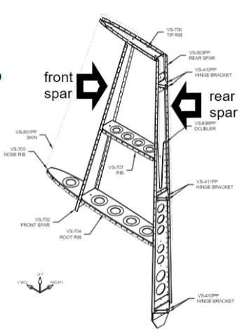
The RV-14 rudder requires a fair amount of precision. Its surface controls aircraft yaw and as an aerodynamic foil it must also be slippery (low drag) as it moves through the air upwards of 200 MPH. The feature to get right, is the trailing edge (TE) which slims to a pointed ending. It must be straight and true without twist.

trailing edge depicted and a desired result

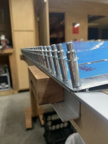
Observe the underlying aluminum angle bar fixed to the workbench in the photo. While the bench itself is quite flat, the aluminum straight edge clamped to the TE will minimize any pucker or wave tendency in the skin. The skin is quite thin (0.016″) and needs the support. A preformed wedge is sandwiched between the right and left skins as you can just make out inside the TE of the rudder (lying on side).

TE wedge

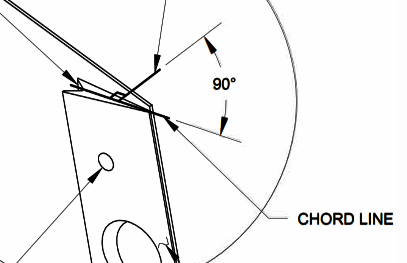
The TE wedge is machined so that its rivet thru holes are angled properly. They are matched drilled 90 degrees with reference to the chord of the wedge. The holes are also machine counter sunk so that the dimpled skin will lie within for an interference fit that also allows the skin to lie flush upon them.

An adhesive seal provides a bond between skin and wedge. Once the sealant cures the cleco clamps can be removed and the sandwich permanently fixed in place by riveting. With this effort the structure will be robust and provide good handling characteristic without adverse yaw or drag whilst cleaving the sky. Straight and true.

Vertical Stabilizer Finale

The VS has been completed. A buck (tungsten bar) in the one hand and a pneumatic gun in the other, fixed skin to skeletal structure. Rivets were placed one by one in the dozens of holes perfectly aligned and previously held fast by temporary cleco fasteners. The gun placed against the manufactured head and the bar against the shop head formed the rivet making each one fast.

Vertical Stabilizer mock up

Inner skeletal structure

Once encapsulated by (0.032) 2024-T3 sheet aluminum the vertical stabilizer will be quite robust. The spars and interconnecting ribs enhance rigidity while retaining light weight. The outer skin will tie it all together. The spars are of the same material spec as the skin. To add backbone i.e. rigidity extra material is strategically employed. This doubler material is of greater thickness (0.125″). You will observe the large diameter holes in the doubler; they are for weight reduction.

Rear spar to doubler finish drilling and rudder hinge match drilling on the RV-14 project

Pre-Punched – In the kit manufacturing process the vendor enhances the product by machine piercing the rivet holes. The machine has a much more precise tolerance than any amateur in their positioning. In this application they are slightly undersize at 1/8″ (0.125)

Doubler – A small piece of plate attached to a larger area of plate that requires strengthening in that location

As described in the video clip the manufactured holes must be enlarged from 0.125 to final size 0.1285 in a process called finish drilling. I use a #30 reamer for this purpose.

A reamer is a rotary cutting tool that is used to enlarge and finish holes that have been drilled, bored, or cored. Reamers are designed to center themselves in an existing hole, which results in a rounder hole and with fewer burrs. 

Thanks to the precision of the pre-punched holes everything generally will line up for excellent fitment. When alignment is crucial a process called match drilling is employed. A piece that already has pre-punched hole(s) is used to center an underlying piece which does not. The former acts as a guide for the drill bit once the two are mated.

RV-14 Amateur Build

Vertical Stabilizer Forward Spar Fabrication

Not without challenges and learning curve, the video for brevity has been somewhat polished. Behind scene lots of investigation, a little practice, and study has occurred. This is the beginning of an amateur build of an experimental (E/AB) Van’s Aircraft.

EAB Experimental Amateur-built is an aircraft built by an non-paid individual and certified by the Federal Aviation Administration (FAA) as “Experimental“. Colloquially known as home-built aircraft and kit-plane, they are typically constructed with acquired tools, a set of plans and parts from kit plane manufacturers.  E/AB aircraft make up nearly 10% of the U.S. general aviation fleet. 

Van’s Aircraft having a solid reputation as a kit provider will be shipping airplane parts from the West coast over a multi-year span for the duration of this project. A first sub-kit has already arrived. The end result when completed will be the RV-14 model.

RV-14 (Flyer Magazine JULY 2021) depiction

The Empennage (first sub-kit) includes the tail cone (fuselage aft structure) and the airfoils affixed thereto:

  • Vertical stabilizer (VS) and attached rudder
  • Horizontal stabilizer (HS) and attached elevators)

Wings, fuselage, firewall forward, engine/prop, finishing, and avionics will follow in progression. There will be ups and downs (idiom and pun) and lots to learn. The experience (06-02) begins!

aero workspace