You’d think that a brand new marine carburetor would bolt on and function perfectly out of the box but I’m finding out that you have to fuss with it. I’m focusing on the Idle circuit because turning the Idle Mixture Screws is having no effect on my less than smooth running engine.
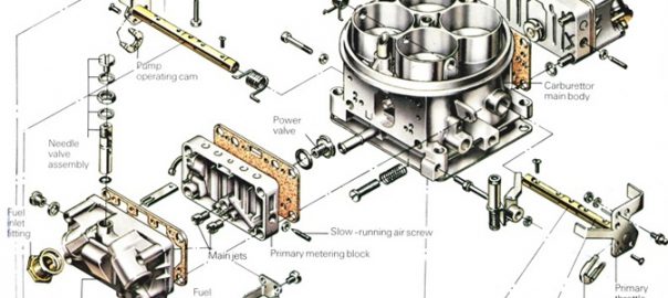
I’ve learned a few things from Randy, a good ol’ boy sharing his sense of experience on a Youtube channel. Studying the intricacies of the casting; all facets to figure the fuel trail and how it gets from here to there, I now know that there are dual routes. See if you are able to follow:
Fuel arriving from the Primary Float Bowl is flow limited by the Idle Feed Restriction (solid yellow arrow). The fuel is drawn upwards through an internal passageway (solid turquoise line arrow) to the top of a parallel downleg (dashed turquoise line arrow) to be split off to the Idle Feed Port and to the Idle Transition Slot. Small air is also introduced via the Idle Air Bleed (solid yellow circle) to mix it up with the fuel traversing the downleg.
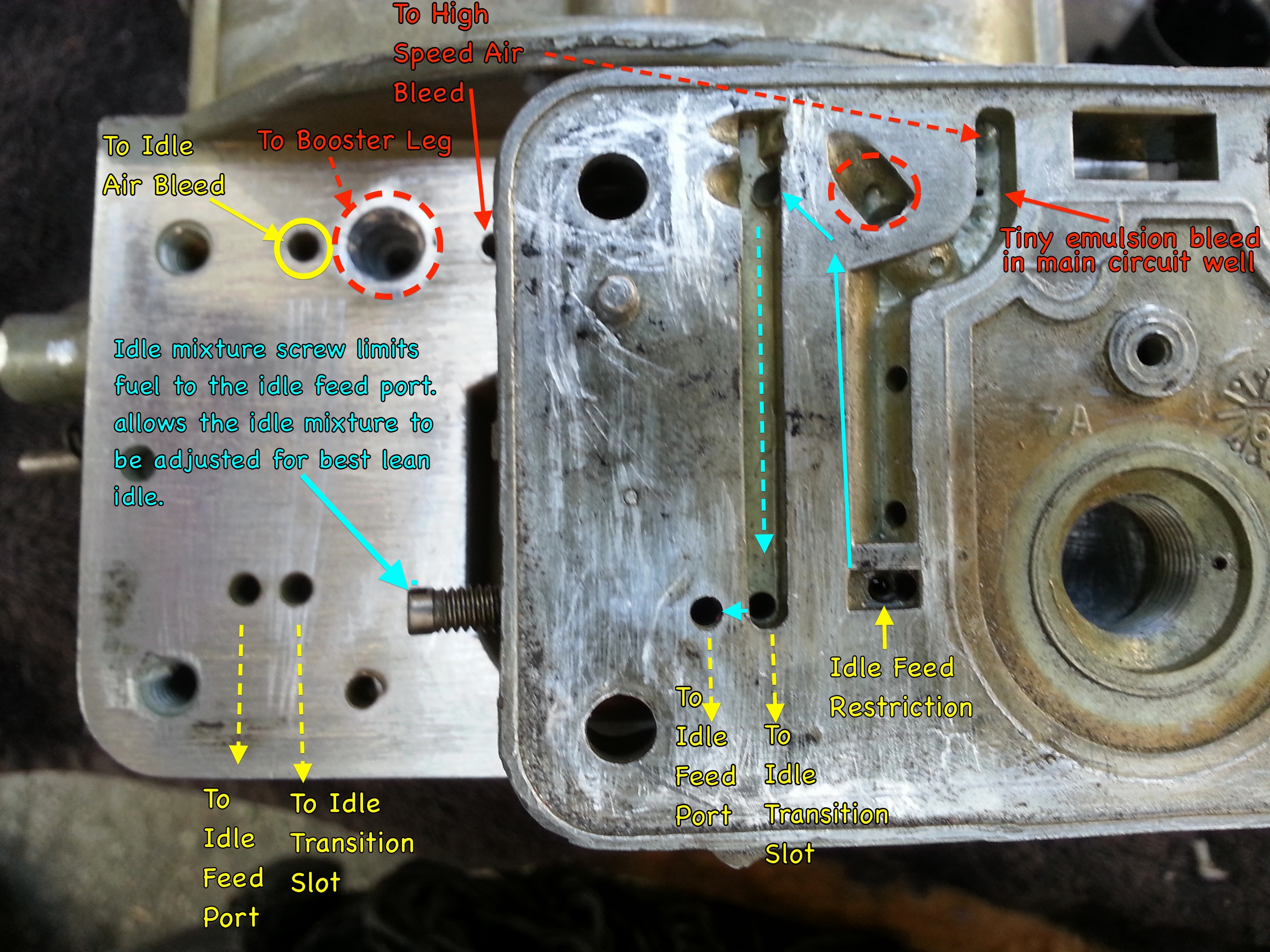
The dual pathway ports (dashed yellow arrow lines) deliver the the air/fuel emulsion to the Idle Feed Port and the Idle Transition Slot in the throttle body below. The throttle body contains large butterfly valves that allow significantly more big air to mix and swirl making a combustible mixture. This [ stoichiometric ] ratio is roughly 15:1
What’s happening with my application is that the throttle valves are exposing too much of the Idle Transition Slot (lower image detail). This has the undesired effect of creating an excessively fuel rich mixture. The Idle Feed Port is not in the game passing little or no air/fuel. 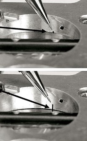 The Idle Transition Slot is doing it all. Allowing the throttle to close down further will hide most of the slot (upper image detail) The Idle Feed Port (the small black dot) will resume its function with the Idle Transition Slot properly obscured. The Idle Mixture Screw can then be brought to bear allowing for precise tuning.
Final consideration: Closing down the throttle valves will by nature reduces the air volume. The engine will stall. In order to restore adequate airflow, a hole (~.080″) must be drilled into each butterfly. It will be trial test with hole size until the ideal diameter is reached. Starting small, I want to get the engine idle RPM into a ballpark range. Fine RPM adjustment can be made with the Idle Speed set screw at the throttle linkage.
That concludes the custom setup mentioned in this post intro. Idle Mixture screws will be controlling at slow idle. The Idle Transition Slot will become effective once the throttle is part open. Keyword is transition. A fuel main circuit gradually provides even more fuel as demand calls in a seamless progression from idle to full power. Keep it smooth.