Not an acronym for an off-putting phrase, in FAA lingo it means withdrawn from use. Occasionally, I run across an early days airframe that I used to fly. These machines may have reached the end-of-the line due to age, component wear limit, abuse or neglect but in some cases, with extra care and good fortune, they might be operationally airworthy and still going.
This green job is still flying the airways. I have stick time in this one only when early on in my career it was liveried in United colors, a 15 seat EMB110P1 N102EB one of a fleet operated by Westair Commuter in California. Re-numbered TG-JCO you’ll note is not a USA registered tail but a Honduran one. We’ve both moved on.
There are significant others that I have tracked down from my office desk: N3053W LJ-613 a Beech King Air that I flew in the 1980’s now operating in South Africa; another King Air N511D LJ-951 operating as PT-OZJ in Brazil. The tail numbers and paint schemes change so if one happened to be physically within eye sight you’d never know it. A useful resource for tracing aircraft is a Dutch website with a database that can reference by registration number or C/N (construction number).
As there are many photographer aviation plane spotters worldwide actively capturing and identifying aircraft and location; it is usually easy to find any particular bird while stalking my Exes with a simple search. Some camera toting enthusiasts even venture into the graveyard.
Sad and at the same time artistic as they return to earth, this boneyard in Bates City, MO turns up dozens of old relics that have many flight hours logged and recorded in my own pilot log book. Pictured is N616KC c/n 110238 “retired” in 1991. There is a DNA resemblance to the green one above. They are of the same fleet type but this one has been stripped for parts.
Not all have been put out-to-pasture. Tragically, a number have been damaged beyond repair — written off. This is a euphemistic way of implying Crashed.
THE LAST RADIO CALL MADE BY THE PLT WAS AT 0658 EST WHEN HE REPORTED LEVEL AT 8000 FT. RADAR DATA AT 0708 EST, SHOWED THE ACFT CHANGING HEADING FROM 327 TO 335 DEGREES, ALT DECREASED FROM 8000 TO 5000 FT AND GROUND SPEED INCREASED FROM 179 TO 188 KTS. COMMUNICATION WITH THE ACFT COULD NOT BE ESTABLISHED AT THIS TIME. RADAR COVERAGE WAS LOST 5 MILES WNW OF SAYRE INTERSECTION. THE ACFT CONTINUED ITS DESCENT COLLIDING WITH POWER LINES FOLLOWED BY THE GROUND. INVESTIGATION DID NOT REVEAL ANY MECHANICAL FAILURES AND/OR MALFUNCTIONS.
That was N806Q a Beechcraft 58 Baron that I flew during happier times and I am sorry to learn of its demise in a morbid way. I logged 523 flights in it. Her sister, N807Q, another bad ending with occupant fatalities.
On a much happier note: N4702X a 1966 year model Cessna 150G still flying!
I had my first flight and solo in N4702X c/n 15064752 [photo credit: SBJ over Watsonville, California]. It still wears the original paint color scheme from memory. At the time (1975) it was part of a small flying club at a small airport in Fresno and this is where it all began.
This visualization of a home automation shows a mesh network of smart switches, smart plugs, and sensors.
The rectangle object in the diagram identifies a Zigbee Coordinator (radio adapter) which is the go-between for the automation hub. Sensor end devices (circular object) that are within close proximity can signal back to the Coordinator directly. Data is transmitted using a low power RF so signal strength is a factor. Happily, since this is a mesh network, the more distant end devices can chain relay through smart devices (oblong object) which relay amplify to the Coordinator like a router.
Having traced our Scandinavian roots we shift to a tougher one to crack; The Harrison side of the family– born into the Russian Empire what is currently Lithuania. Difficult because there was little to go on. We had first hand knowledge of those who were born in the USA of course but their parents that immigrated and who had enjoyed good lives here were loath to talk about their past. In other words any hard facts were not forthcoming. We did not have places of birth, dates, or even their former names and spellings.
Nanny Fan dismissed most inquiries, saying that her last memories of the old country were too distressing to re-live. We believe she probably witnessed religious prejudice, cruelty and even bloodshed. There were hints that some emigrated with just the clothes on their backs and valuables hand stitched into coat linings.
We think our relatives from the old world would have wanted to assimilate as citizens into the USA not only to avoid scorn or ridicule but to gain a normalcy that would not sabotage their sense of community or livelihood. First order of self help: losing a foreign sounding name and learning English. So, none of us twice removed had good intel.
We had but one strong hint: the original family surname sounded like “Kurgon”. So where to begin…
Working backward with the closest relative, father or mother, we find out who their parents were and in this case learn that Zadie’s father, Max Boris Harrison had immigrated. Starting with a 1910 United States Census we scrape the year of immigration (1908) and discover that he, with parents and siblings, were under the same roof in the USA by 1910. It was likely that they immigrated together as well; but what surname? Harrison was the naturalized but how to search for this family in archival ship passenger listings?
A challenge is that invariably each tracking document has the names malformed in some way. Not only were names changed but then altered or misspelled through clerical error along the way. The Census poll has the name as Herrison. Sifting through passenger lists would have been and impossible task before searchable computer databases. Realize that a data set was once transcribed by human hand from records hand written and with hopeful accuracy. In our case Harrison turns up zilch. Luckily a search engine allows for fuzzy or broad pattern name spellings. Browsing dozens of returns we capture a hit with a Max Herison. And with a departure port of Hamburg, Germany it makes sense. A bit of sleuthing reveals that this was close proximity and the natural point for anyone emigrating from the area now known as Lithuania. A German document processor upon hearing Harrison phonetically would have written down Herison. The German word Herr (a conventional title showing respect when addressing a German gentleman translated as Sir or Mr. and sounds like “hair”) so naturally a local clerk might trade the letter e for the a. His counterpart in New York would switch it back from e to a!
SS Kaiserin Auguste Victoria – Passenger List
Observe Max B, his mother Rose, and younger sisters Dora, Lena, and Hannah all together. (Father: Morris immigrated in 1904) Their ship makes interesting historical reading. It was operated by the Hamburg-Amerika Line and they traveled Steerage Class on the 9 day voyage to New York.
So we now know Hamburg. Our family boarded with their new surname Herison but the trail goes cold again. Searching the old name Kurgon reveals little except that an alternate spelling, Kurgan, offers many hits but with another obstacle. The first/middle name Max Borris would need to be translated along with everyone else’s given names. Mother, Rose was Rasha or Rasya in the old world. Dora Sarah was Sore Dvora. Morris Harrison was Movsha and had many name variations but ultimately was to become Morris. Max Boris birth name was Berel Mordekhay. That one was never going to turn up even with the broadest of search variations. There was better luck with his father’s name which helped to pinpoint him with the other family members.
Finally, having the names we could find places and dates. Browsing the LitvakSIG online data source for taxation, conscription, and family list ledgers was fruitful.
The central government did in fact run a comprehensive Census back in the day, which would have been most excellent for our purposes except that they only retained population counts and counts by ethnic percentage — discarding all the other details. Shoot.
Armed with a a place, also with spelling variations depending on nationality, required some geo-political learning. In the USA we have town|county|state with maybe a rural township to complicate the effort. The Russian Empire used province|district|town as we drill down. One aspect is that modern political borders and alignments are significantly less helpful. Lithuania for example wasn’t a thing before WW I but listing a country location as Russia does not work either. One must find and utilize period correct maps.
Russian Empire Provinces of Kovno, Vilna, Suwalki until 1918
These old time provinces today would encompass Lithuania and spill into current day Belarus and Poland. Our Kurgan (Harrison) group lived in Vilkija which is on the Nemunas River in the province of Kovno district of Kovno. An alternate spelling, Kaunas, is synonymous. The former is Russian and Lithuanian is the latter. Here we find our relatives and discover some who didn’t make it to America.
By the time we, as descendent children, take interest and get around to inquiring about family background history — direct informational account is no longer possible and by now second/third hand news. Logistically, one’s closest living relative was probably a youngster themselves (Nanny Fan was age 5) when she and her family emigrated and she would have had scant primary recall. She would have instead relied upon stories or tales after the fact and that these recollections may have been influenced by blur, bias, or emotion.
So the old family backstories were easily contorted or even lost all together. It’s interesting to uncover them in the perspective of historical times past and with a perceived glimpse into what once was.
In sympathy with peoples abroad who might be chilling these next few months and in consideration of rising energy costs closer to home I am implementing a new routine with hopes for conserving.
The first step is to adopt a “time of use” billing strategy that utility companies offer. The utility solicits a pricing incentive for customers to refrain from and reduce consumption during the part of day that is historically prime time for energy usage. My humble abode is equipped with a heat pump and that is a big consumer so I give you the following strategy:
On-peak is from 6 a.m. to 9 a.m., Monday through Friday excluding holidays, so I don’t intend to use the heat pump(s) or worse — system AUX heating, a big draw item. So to comply, the thermostat will be turned down for this time slot. To mitigate rise and shine shivering or breakfast hour discomfort the living space will be pre-heated using the Off-peak ($0.067) rate before it cuts off. On-peak is a penalizing $0.39 per kilowatt hour and to be avoided.
thermostat – settings
0500-0600 74 degrees (pre-heating)
0600-0900 65 degrees (On-peak)
0900-1600 68 degrees
1600-2145 72 degrees
2145-0500 65 degrees
A Smart Thermostat simplifies the task of micromanaging the setting adjustments.
extra credit
Ensuring that the water heater, also electric, will never draw current during the On-peak is a bit more involved but easily controlled. A relay to open/close the 240v contactors for the heating element can be actuated by a 120v smart plug. An [smart-hub] automation routine then will pause the appliance like a timer.
future plan
There is a Super Off-peak between the odd hours of 10 at night and 5 in the morning. At a mere $0.043 cents per kWh this will be an opportune time period to charge the EV.
maybe…
At some point go off grid? Solar array? Powerwall? In any event, please stay warm.
Our Irrigator uses an old school shovel; poking a hole, looking at dirt. With the installation of our new Irrometer IRROcloud IC-10 we can perform the same task and from afar — no shovel necessary.
An array of sensors buried in the active root zone measure soil water tension. A sensor is an electrode embedded within a specialized granular matrix. Water in the soil exchanges with the matrix, providing an electrical measurement of soil water tension expressed in centibars (or kPa). Sounds like magic. These sensor readings are captured by a data logger and uploaded via cellular to the Cloud allowing us a real-time inspection.
West Block – Muscat
This is actual output from 20 JUL through 01 AUG looking at the 1 foot depth sensors. Moisture is depicted on the Y axis. The X axis shows the individual days.
The [gray] line is an average of the moisture sensors in the root zone and the [blue] bar graph(s) are recorded irrigation events. The upper band of the chart equates to DRY and the lower scale WET. Observe that the typical peaks and valleys correspond to the heat of day and coolness of night. The significant dip (valley) concluding an irrigation set shows a dramatic increase in soil moisture.
The general idea of course is to manage the irrigation; keeping the moisture level within an ideal (white band) range. But, we shall quantify this with the following graphic:
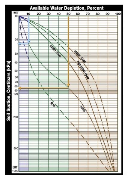
example depicts the Loam soil type
10% depletion of available moisture will determine the WET reference value. 50% is a generalized recommendation for a DRY depletion threshold (point where a plant can not easily extract remaining moisture from the soil without stress)
Based uponour Sandy Loam soil one can use the graph to determine the desired moisture range. Entering the chart at 10% and dropping vertically to the correct soil type curve and then coming across horizontally the result would be: 14 centibars as the wetter threshold. Doing the same only entering at 50% on the dry end equates to 40 centibars. [see basics] in between 14 and 40 centibars (the white band) should yield vigorous thriving vines.
This next image is the irrigation tabulation showing the 5 data sets reference the bar chart atop.
Irrigation SetsGreen data line is a 1′ depth sensor Blue data line is a 2′ depth sensor
This zoomed section shows an inefficiency during the 27-28 JULY irrigation event. The drip system was running for too long (18 hrs.) sending water below the root zone; wasted. The previous set on 26 JUL with a 6.8 hour duration was more elegant (excepting the 0.6 hour subsequent false start).
20-25 centibars might be a good upper end target to begin an irrigation. How did our Irrigator do? Keeping the moisture within an acceptable band was achieved albeit a tad on the wet side being careful perhaps. Not bad considering the shovel method.
Simulator flying mimics the real thing. Display visuals show realism. There are sound effects for engine and other aircraft equipment noises. The aircraft cockpit flight controls, switches, indicators, and instruments are identical to those of the actual cockpit. Since the machine is perched upon electric actuator struts that can raise, lower and tilt the box in all axis “G” forces are mimicked. Vibrations can be discerned when taxing across tarmac expansion joints or the thump thump thump encountering flush mounted runway centerline lights during takeoff roll.
The simulator doesn’t actually have landing gear or wheels but amusing when you realize that the device has tricked you into believing that it sure seems like it does. The interaction between brain, eye, small of your back, seat of your pants largely takes you in. When applying brake pressure for instance the simulator box dips forward which allows a sensation of deceleration. But the inner ear is not perfectly fooled. Steering a 90 degree turn on an airport taxiway can be nauseating. It is best not to stare too hard at the video presentation in the cockpit window. (When it’s my turn in the co-pilot seat, I don’t even look; keeping eyes in.)
Despite the nitpicks, the experience is real enough and deemed by the regulators to suffice for full blown training and qualification testing. A new pilot will complete the course regimen solely in this device and obtain his Aircraft Type Rating without having boarded the actual airplane before. His first flight (non-simulated) may even have [oblivious] passengers onboard!
A crucial advantage of simulator flying is that many “what if” events can be experienced without putting man or machine at physical risk. Challenging scenarios can be allowed to play out to successful outcome. Before the adoption of advanced full motion simulation, emergency drills where “simulated” in an airborne aircraft. An instructor pilot would surreptitiously reach for an engine power lever and snap it closed to observe a pilots response procedure. This usually worked out fine, as long as everyone stuck to a certain script. Multi-engine aircraft can fly just fine with an inoperative engine. On the other hand; what could possibly go wrong there?
V1 Cut
This is the demonstration of pilot reaction and the control that is necessary because even though, an aircraft is designed to climb engine out it can go badly if not performed precisely. With a failed engine the thrust centerline is now asymmetric. The aircraft wants to yaw and turn in the direction of the dead engine. There are usually terrain or air traffic control considerations so there may be undesired consequences should the aircraft drift off course suddenly or otherwise. The episode is almost always practiced at V1 (decision speed — the point where there is not enough runway remaining to abort the takeoff and at which you are now committed to take it into the air ) It is a velocity calculated beforehand and a commitment rigidly adhered to. This point is the most challenging moment for an engine “Cut” and the engine can lose thrust gradually (called a roll-back) or altogether as in catastrophic failure (associated with a loud bang)
The pilot’s (PF — pilot flying) first task is to counter immediately and correct with opposite rudder. The direction of the yaw may come into eye view as the nose of the plane tends to depart the runway centerline and aims itself for the green grass off pavement. The rudder pedal is used to restore directional control. The rudder surface has low effectiveness at this speed so a massive deflection is necessary; meaning with exertion you push your foot all the way to the floor holding it there. Your scan moves from outside to instruments on the inside because, recall we also had to get airborne and we have simultaneously rotated the aircraft into a pitch up movement to do so. The pilot’s attention is divided across directional control, pitch attitude, and [V2] airspeed. The tolerances are narrow. With disciplined scanning, proper assessment and deft control placement a desired result happens — laterally and vertically. With a positive rate of climb the pilot brings in the second pilot as a resource. This pilot {PM — pilot monitoring) verifies and calls out “positive rate”. The PF calls “gear up”. The entire script is well choreographed and each pilot knows exactly what each is expected to say and do and when. We call these [memorized] actors’ lines.
We are not out of the woods yet. As the aircraft accelerates the rudder gains effectiveness and therefore less deflection is required. The PF constantly adjusts his leg pressure thus maintaining coordinated flight and managing desired heading. A previously calculated [takeoff] flap retraction altitude is reached and the PM announces “FRA”. The PM accelerates the aircraft to the faster and appropriate [Vfs] climb speed and commands “flaps zero”. The climb continues to the briefed safe altitude at which time emergency checklists are performed, ATC advised and their resources utilized. A plan of action is decided upon and briefed and so it goes.
This kind of actual event is extremely rare. I’ve only experienced an engine failure once in my flying career (through 4,000′ on climb out) but just the same we prepare for it and the simulator is an ideal stage.
Elec XFR Fail
This is another time critical event. In the rare occurrence of a dual gen fail and in an effort to conserve battery power the automation will reconfigure the system to shed nonessential loads. CAS warning/caution messages post to the PFD but the bigger give away is the dark cockpit with loss of lighting and blank display screens. You’ve lost a host of other systems too –everything on DC BUS 1 and DC BUS 2 (pitch trim norm and pitch trim bkp — oh dear) In this electric transfer fail scenario, the described reversion didn’t automatically happen and, time critical, because battery life will be severely impaired.
a generic Embraer QRH flow chart for transfer failure
Time is of the essence. The Quick Reference Handbook (QRH) directs the PM to press the ELEC EMER Button, the manual method which overrides the EPGDS, connecting BATT 1 and BATT 2 directly to the EMERGENCY BUS. If this was successful you’ve bought some time but you’re still dealing with the lesser of the two evils, the ELEC EMERGENCY [CAS]. The PF has got his hands full trying to maintain pitch control. (The simulator instructor gave us this one right after takeoff so the aircraft/sim was nose high on trim. I could only arrest the climb by wedging by knee into the control yoke providing thigh muscle assist.) The PM is still in the QRH with the next CAS as the aircraft/sim cabin pressure is escaping and will soon manifest another set of issues. In hindsight, because of our low altitude, we could have cut to the chase and zoomed to the final checklist line; giving my arms a break:
Generators 1 and 2 .................. OFF, THEN AUTO
This ultimately reestablished things as one of the generators came back online. I had my instrumentation and pitch trim and systems restored.
Good thing to demonstrate and to see — in a simulator that is.
A-I WINGSTB LEAK
This cautionary CAS alert directs the PM to a checklist flow chart to try and isolate the source of a bleed leak. Bleed is high pressure air that is used for cabin pressurization, ECS, and airframe anti-icing. Air gains heat when compressed so hot bleed impinging upon unprotected structure is bad. Through the process of elimination we were able to switch to off the errant bleed. The QRH gave further direction to leave icing conditions whilst recommending necessary precaution for degraded performance for the approach and landing phase with Flaps limited to Flaps 1.
We executed and uneventful touchdown at the Pittsburgh Intl Airport — simulated naturally.
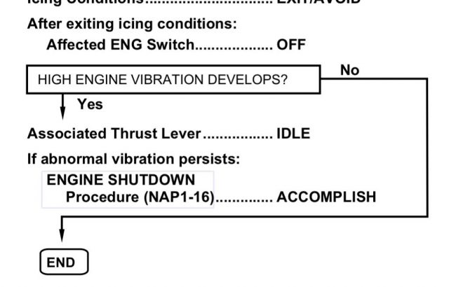
A-I E1 (2) FAIL
We saw this one; the anti-ice engine 2 fail CAS. Noticeable vibration developed (yes, the sim does) but before we could action the NAP1-16 reference procedure the engine spooled down. This led to an engine inop approach and landing exercise.
Rules of the Game
Each scenario practiced results in a successful outcome. That of course is desired as it gives good experience should such an event play out in actuality. Positive training.
The sim instructor is not allowed to over-task the pilot with multiple scenarios, at least not at the same time. A windshear situation or terrain escape maneuver would never be compounded with a loss of cabin pressure as an example. Problems can and do coexist of course. e.g. engine fire > single engine approach to landing So, each problem is carefully worked through logical step by step to conclusion before another one begins.
The order of problem solving is by priority importance. For instance, you might think that the first concern during an engine fire is to fight the fire but that is not the case. Number one is to fly the airplane. Maintain control.
After reaching a [briefed] safe altitude we may be required to perform an emergency checklist from memory or Quick Reference Checklist (QRC), or QRH in that order, then we deal with the more “mundane”. Memory items cover immediate action items:
Cabin smoke
Cabin depressurization
Dual engine failure
Inadvertent pusher activation
Evacuation
Start Malfunction
After a 2 hour drill we generally take a 10 minute pause and then swap seats to finish with another 2 hours of excitement. Thus ends the sim session. There are 236 unique CAS messages that lurk so there will always be stuff to see for the next time.
A computer screenshot is trivial today. Using software or even simple button press of PRT SC on the keyboard. But, the terminology comes from the act of literally taking a picture of the screen — the television screen that is.
B&W televised demonstration of working steam engine recorded in the first grade classroom and broadcast as local news.
Using a hand held [Argus C3] film camera in 1958, the resulting capture lost contrast clarity as it was a copy of a copy. (a flatbed scanner was used to scan the original photographic print just posted here so a copy of a copy of a copy) The light would have to be right as the camera would not have had automatic exposure and any glare or refection on the TV screen minimized. Camera focus would be a consideration; pre WYSiWG. Though grainy, it was a resourceful method and the proud parental event was luckily/successfully recorded.
We have it easy. SAVE AS would have archived the entire video and WITH sound, but back in the day this screenshot example was high tech.
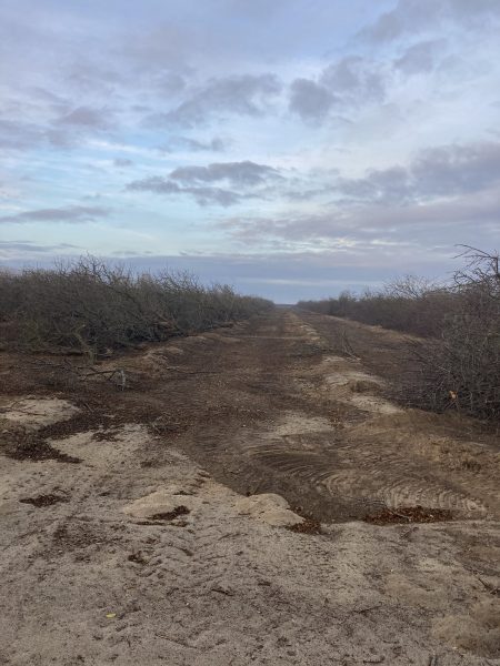
The almond orchard removal process has begun. It was time. The conjunction of declining harvest yield and profit spread was the impetus.
as of 12/26/2020 one row gone…
The orchard, originally planted in 1998 by tenant farmer Jagpal Bath, had a tough time of it in those early years. The orchard had been abandoned and was nearly doomed when in 2001 Estee Strom foreclosed and undertook matters; successfully reversing the neglect and reviving the trees.
Our trees have served us well, but almond orchards by nature have a lifespan of 25-30 years. The main factor in an almond trees lifespan is, of course, productivity. A new almond tree normally begins to produce at age 4 or 5 and achieves a yield plateau by year 15. After that it starts to slowly decline.
Routinely, diseased or aged trees that succumb to springtime wind storms can be replaced with replants but in the last several years this kind of tree loss was accelerating and alarming.
Orchard removal and replacement is capital intensive so our decision to proceed at this time has not been trivial. Tracking and comparing yields over time provided some analytical guidance. Also, market pricing. When the payoff approaches break-even or threatens to dip below our decision solidified. Based upon trends a 2021 crop likely would have resulted in operational losses.
Following the decision, necessary contracts and permitting started the process. The irrigation drip lines were rolled up and removed from the tree berms. The trees are “pushed over” by heavy equipment. Another machine will lift them ( 14,294 at last count ) individually into a mechanical basket designed to shred and chip roots, branches and sizeable trunks into manageable bits. A cheaper alternative would have been to mass the trees into pile heaps for burning but our aim is to incorporate them into the land as a green mulch. This will be better for air quality, obviously, and also give back to the soil.
And so, the cycle repeats. We farmers look forward to establishing our next crop enterprise as plans formulate and the orchard removal process proceeds.
This Strombotne family surname has always been a twister. Some get it right first try but others, be they strangers or acquaintances could attempt — make a hash of it and give up or not even try for fear of mangling and risking insult injury. The first syllable was generally easy for them but the rest of it, usually a big fail. Frequently the “t” gets ignored for some reason and it’s uttered phonetically : strom·bone·eeee . Cringe. I had a Junior High PE Coach that would say it Strum·bot·knee with the emphasis on the second syllable. He had the last 2/3rds correct but the first syllable came out like strum (as in strum guitar).
Here’s how: Strom begins with an ST blend phonic same as do words straight or strong and these two consonants precede rom which sounds like ROM (computer read only memory) or rom as in Trombone (the instrument(s) from The Music Man) then bot like in robot and finally “ne” — say knee (the knee bone connected to the…) Strom·bot·ne
Then we have spelling tangles. After they’ve heard the name spoken there is the issue of the last letter. Was that an “i” followed by conversation: “Oh! is that Italian?” No it’s a letter “e”.
Strombotne is an anglicized family name tracing its origin to a farm in Norway — Straumbotn.
Ancestors that lived at Straumbotn and elsewhere had been using a patronymic naming system. The use of a fixed family name was made compulsory by law in Norway in 1923. As a result of this change, many chose and began using their patronymic name as their fixed family name; others (as in our case) chose their farm’s name as their permanent family name and thus the surname name — Strømbotne.
Patronymic Simplified: A child’s last name was derived from the father’s first name. If you had a daughter you would add – datter to the end of the father’s first name, if you had a son you would append – sen or –son to the father’s first name and this new name compounded would become the Childs surname. Sometimes the name of the farm was used as a 3rd name; not so much as a surname but as an address identifier. The reason being is that after several centuries many now had the same first and last names. A formal change to a fixed family surname began in the early 1800’s and was widespread by about 1900.
Spelling differed but the sound was always the same. Straum was the (Nordland local) Nynorsk standard and Strøm was the Bokmål way (Danish was the written language of Norway until 1814).
Considering authenticity, I doubted that my ancestors pronounced words anything like we do here in the USA. Then I told a Norwegian friend, last name Tvedt 🙂 of my state of perplexity and asked him to read it into a recorder.
Strømbotn
We think that other peoples in broader Scandinavia had been adding a soft “neh” sound to botn, so Strømbotn gained an “e” in its spelling to align with this pronunciation. A second theory is that since there are no English words that end in “tn” consonants that this vowel was added to the spelling. Somewhere along the line the soft “e” (neh sound) became a hard “E” (sounding like knee) the spelling Rule #3: the silent “e” ignored evidently.
After an ah hah! moment of imagining a lifetime spent methodically (incorrectly) correcting people it became clear to me that my instilled conception of pronunciation wasn’t necessarily THE way .
In the case of brief person to person interaction it’s unlikely to matter too much how you pronounce it. No longer do I impose (unless badly adulterated) and even then at times let them know “close” or “good effort” as it gives them satisfaction and allows them to smile. But, for standardization (and extra points) say Strombotne – – – strom·bot·ne, straum·botn, or possibly straum·boat·neh.
The church registers from this old parish, and others like it, documented life events for many that came before us. Over recent years these church books have been carefully digitized and archived. They make for interesting sleuthing when seeking out generational family relatives.
The Hemnes Church (photo circa 1890-1900) stands today. Its church grounds contain the original cemetery that was last used in 1886. I have kinfolk buried there.
To this particular church, Great-Great Grandfather Christopher Olai would row his open fishing boat in order to attend the Sunday service.
Looking at that…
period correct fishing craft
No, not the parish parking lot but the very active fishing village of Lofoten. Grandfather’s traditional style boat probably resembled one of these centuries old Nordland craft. It has a high prow and stern similar related to he old Viking longships.
Seksringsbåt med seil og dregg, Lofotbruk
Translation: six-ring boat with sail and dredge, Lofoten use. A craft like this was census listed as owned by Great-Great-Great Grandfather Johannes. This boat was all serious and no play, a bit heavy to row single-hand. Likely, son Chistopher Olai had something svelte (a two-ring) if he went by himself.
His 8 1/2 mile (bi-directional) endurance route through Norwegian fjords would have been quite the scenic (spiritual?) journey. Øverstraumen is a fjord arm of the Ranfjorden, Commencing at the Northern bottom of this fjord arm at Straumbotn and after a narrow bit (Nordgården) there is an exit outlet at Straumkjeften strait in the South. The Ranfjorden opens to the sea eventually but Christopher Olai’s trek would terminate at the narrow strait at the Hemnesberget village.
Impressive! — bragging rights among the parish group. For one of Us, this would be a major feat but for Olai it was Sunday’s health exercise ritual. He was a fit fisherman so he might just parlay wind and water currents to advantage. That, and perhaps a greater power watching over.