Category Archives: flying

Keeping Things Straight

The RV-14 rudder requires a fair amount of precision. Its surface controls aircraft yaw and as an aerodynamic foil it must also be slippery (low drag) as it moves through the air upwards of 200 MPH. The feature to get right, is the trailing edge (TE) which slims to a pointed ending. It must be straight and true without twist.

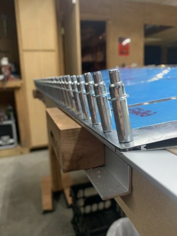
trailing edge depicted and a desired result

Observe the underlying aluminum angle bar fixed to the workbench in the photo. While the bench itself is quite flat, the aluminum straight edge clamped to the TE will minimize any pucker or wave tendency in the skin. The skin is quite thin (0.016″) and needs the support. A preformed wedge is sandwiched between the right and left skins as you can just make out inside the TE of the rudder (lying on side).

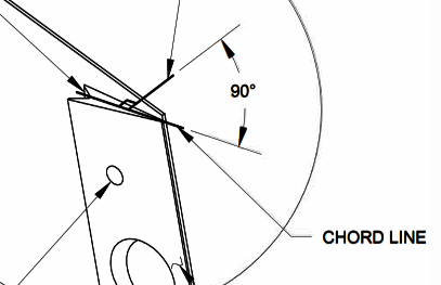
TE wedge

The TE wedge is machined so that its rivet thru holes are angled properly. They are matched drilled 90 degrees with reference to the chord of the wedge. The holes are also machine counter sunk so that the dimpled skin will lie within for an interference fit that also allows the skin to lie flush upon them.

An adhesive seal provides a bond between skin and wedge. Once the sealant cures the cleco clamps can be removed and the sandwich permanently fixed in place by riveting. With this effort the structure will be robust and provide good handling characteristic without adverse yaw or drag whilst cleaving the sky. Straight and true.

Continued VFR

Fraught with the risk, a scud running pilot conducting a flight that started out under VFR may blunder into IMC conditions. The outcome is known as and described by the catchphrase continued VFR.

In a foray to get across the Sierra my hope was to have a “look-and-see” as it was obvious from official reports as well as my observation on the ground from the flat valley floor that mountain tops were likely to be obscured. My plan was to depart and follow the North Fork of the San Joaquin which would traverse the range and lead to the Mammoth Pass. At 9,300 ft. elevation this is the lowest point at the ridge for over 250 miles. I’d crossed there many times during routine visits to the MMH airport so I knew it visually. But today it wasn’t visible from start. I launched pretending that there’d be a break in the clouds as a possibility.

There’s the option to fly VFR over-the-top [of the clouds] but this assumes the there will be a clearing or at least a hole to descend through at point B. My Centurion P210N, while very capable altitude performance wise was ill-equipped for an in-cloud icing conditions encounter so I elected to stay underneath the deck.

Barreling up the North Fork canyon it was apparent that the cloud ceiling was solid. However, I still met separation criteria from both cloud and terrain so I pressed onward. Emotional stress began to factor in. The hope for a light at the end of the tunnel was not assured and further the undercast was a grey mass. In fact, to the left and the right was plenty gloomy with the canyon walls merging with cloud. I routinely swung my vision to assess. The Centurion has a back window and this scan included looking behind to verify that my completed route was still re-traceable. I found myself becoming increasingly concerned, not so much with what was ahead, but what was behind. I was relying upon a 180 degree turn route escape. That backup was becoming less assured as I pressed forward.

Canyon flying presents the peril of getting boxed in meaning U-turn collision with canyon wall. Further, that lovely diminishing tight circle of clear daylight aft was becoming quite small. Maintaining visual with the mountainous terrain was crucial and going IMC at this juncture could not be good at all. The grey tunnel surround was bleak.

I learned about flying from this. The trap of continued VFR was raring to bite. Finding relief and dumping the anxiety, I aborted and turned back.

If you don’t like the mountain weather – wait a few minutes (hyperbole). I returned to base for re-fuel and flew an alternate mission plan. All the wiser, this was the safe course and a successful outcome. Discounting expectation bias will help a pilot to avoid a continued VFR pitfall.

Vertical Stabilizer Finale

The VS has been completed. A buck (tungsten bar) in the one hand and a pneumatic gun in the other, fixed skin to skeletal structure. Rivets were placed one by one in the dozens of holes perfectly aligned and previously held fast by temporary cleco fasteners. The gun placed against the manufactured head and the bar against the shop head formed the rivet making each one fast.

Vertical Stabilizer mock up

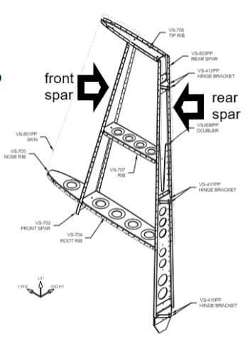
Inner skeletal structure

Once encapsulated by (0.032) 2024-T3 sheet aluminum the vertical stabilizer will be quite robust. The spars and interconnecting ribs enhance rigidity while retaining light weight. The outer skin will tie it all together. The spars are of the same material spec as the skin. To add backbone i.e. rigidity extra material is strategically employed. This doubler material is of greater thickness (0.125″). You will observe the large diameter holes in the doubler; they are for weight reduction.

Rear spar to doubler finish drilling and rudder hinge match drilling on the RV-14 project

Pre-Punched – In the kit manufacturing process the vendor enhances the product by machine piercing the rivet holes. The machine has a much more precise tolerance than any amateur in their positioning. In this application they are slightly undersize at 1/8″ (0.125)

Doubler – A small piece of plate attached to a larger area of plate that requires strengthening in that location

As described in the video clip the manufactured holes must be enlarged from 0.125 to final size 0.1285 in a process called finish drilling. I use a #30 reamer for this purpose.

A reamer is a rotary cutting tool that is used to enlarge and finish holes that have been drilled, bored, or cored. Reamers are designed to center themselves in an existing hole, which results in a rounder hole and with fewer burrs. 

Thanks to the precision of the pre-punched holes everything generally will line up for excellent fitment. When alignment is crucial a process called match drilling is employed. A piece that already has pre-punched hole(s) is used to center an underlying piece which does not. The former acts as a guide for the drill bit once the two are mated.

RV-14 Amateur Build

Vertical Stabilizer Forward Spar Fabrication

Not without challenges and learning curve, the video for brevity has been somewhat polished. Behind scene lots of investigation, a little practice, and study has occurred. This is the beginning of an amateur build of an experimental (E/AB) Van’s Aircraft.

EAB Experimental Amateur-built is an aircraft built by an non-paid individual and certified by the Federal Aviation Administration (FAA) as “Experimental“. Colloquially known as home-built aircraft and kit-plane, they are typically constructed with acquired tools, a set of plans and parts from kit plane manufacturers.  E/AB aircraft make up nearly 10% of the U.S. general aviation fleet. 

Van’s Aircraft having a solid reputation as a kit provider will be shipping airplane parts from the West coast over a multi-year span for the duration of this project. A first sub-kit has already arrived. The end result when completed will be the RV-14 model.

RV-14 (Flyer Magazine JULY 2021) depiction

The Empennage (first sub-kit) includes the tail cone (fuselage aft structure) and the airfoils affixed thereto:

  • Vertical stabilizer (VS) and attached rudder
  • Horizontal stabilizer (HS) and attached elevators)

Wings, fuselage, firewall forward, engine/prop, finishing, and avionics will follow in progression. There will be ups and downs (idiom and pun) and lots to learn. The experience (06-02) begins!

aero workspace

WFU

Not an acronym for an off-putting phrase, in FAA lingo it means withdrawn from use. Occasionally, I run across an early days airframe that I used to fly. These machines may have reached the end-of-the line due to age, component wear limit, abuse or neglect but in some cases, with extra care and good fortune, they might be operationally airworthy and still going.

This green job is still flying the airways. I have stick time in this one only when early on in my career it was liveried in United colors, a 15 seat EMB110P1 N102EB one of a fleet operated by Westair Commuter in California. Re-numbered TG-JCO you’ll note is not a USA registered tail but a Honduran one. We’ve both moved on.

photo credit: Gerrit Griem

There are significant others that I have tracked down from my office desk: N3053W LJ-613 a Beech King Air that I flew in the 1980’s now operating in South Africa; another King Air N511D LJ-951 operating as PT-OZJ in Brazil. The tail numbers and paint schemes change so if one happened to be physically within eye sight you’d never know it. A useful resource for tracing aircraft is a Dutch website with a database that can reference by registration number or C/N (construction number).

As there are many photographer aviation plane spotters worldwide actively capturing and identifying aircraft and location; it is usually easy to find any particular bird while stalking my Exes with a simple search. Some camera toting enthusiasts even venture into the graveyard.

photo credit: Jay Dee Kay

Sad and at the same time artistic as they return to earth, this boneyard in Bates City, MO turns up dozens of old relics that have many flight hours logged and recorded in my own pilot log book. Pictured is N616KC c/n 110238 “retired” in 1991. There is a DNA resemblance to the green one above. They are of the same fleet type but this one has been stripped for parts.

Not all have been put out-to-pasture. Tragically, a number have been damaged beyond repair — written off. This is a euphemistic way of implying Crashed.

THE LAST RADIO CALL MADE BY THE PLT WAS AT 0658 EST WHEN HE REPORTED LEVEL AT 8000 FT. RADAR DATA AT 0708 EST, SHOWED THE ACFT CHANGING HEADING FROM 327 TO 335 DEGREES, ALT DECREASED FROM 8000 TO 5000 FT AND GROUND SPEED INCREASED FROM 179 TO 188 KTS. COMMUNICATION WITH THE ACFT COULD NOT BE ESTABLISHED AT THIS TIME. RADAR COVERAGE WAS LOST 5 MILES WNW OF SAYRE INTERSECTION. THE ACFT CONTINUED ITS DESCENT COLLIDING WITH POWER LINES FOLLOWED BY THE GROUND. INVESTIGATION DID NOT REVEAL ANY MECHANICAL FAILURES AND/OR MALFUNCTIONS.

That was N806Q a Beechcraft 58 Baron that I flew during happier times and I am sorry to learn of its demise in a morbid way. I logged 523 flights in it. Her sister, N807Q, another bad ending with occupant fatalities.

On a much happier note: N4702X a 1966 year model Cessna 150G still flying!

I had my first flight and solo in N4702X c/n 15064752 [photo credit: SBJ over Watsonville, California]. It still wears the original paint color scheme from memory. At the time (1975) it was part of a small flying club at a small airport in Fresno and this is where it all began.

Phenom SIM Ride

Simulator flying mimics the real thing. Display visuals show realism. There are sound effects for engine and other aircraft equipment noises. The aircraft cockpit flight controls, switches, indicators, and instruments are identical to those of the actual cockpit. Since the machine is perched upon electric actuator struts that can raise, lower and tilt the box in all axis “G” forces are mimicked. Vibrations can be discerned when taxing across tarmac expansion joints or the thump thump thump encountering flush mounted runway centerline lights during takeoff roll.

The simulator doesn’t actually have landing gear or wheels but amusing when you realize that the device has tricked you into believing that it sure seems like it does. The interaction between brain, eye, small of your back, seat of your pants largely takes you in. When applying brake pressure for instance the simulator box dips forward which allows a sensation of deceleration. But the inner ear is not perfectly fooled. Steering a 90 degree turn on an airport taxiway can be nauseating. It is best not to stare too hard at the video presentation in the cockpit window. (When it’s my turn in the co-pilot seat, I don’t even look; keeping eyes in.)

Despite the nitpicks, the experience is real enough and deemed by the regulators to suffice for full blown training and qualification testing. A new pilot will complete the course regimen solely in this device and obtain his Aircraft Type Rating without having boarded the actual airplane before. His first flight (non-simulated) may even have [oblivious] passengers onboard!

A crucial advantage of simulator flying is that many “what if” events can be experienced without putting man or machine at physical risk. Challenging scenarios can be allowed to play out to successful outcome. Before the adoption of advanced full motion simulation, emergency drills where “simulated” in an airborne aircraft. An instructor pilot would surreptitiously reach for an engine power lever and snap it closed to observe a pilots response procedure. This usually worked out fine, as long as everyone stuck to a certain script. Multi-engine aircraft can fly just fine with an inoperative engine. On the other hand; what could possibly go wrong there?

V1 Cut

This is the demonstration of pilot reaction and the control that is necessary because even though, an aircraft is designed to climb engine out it can go badly if not performed precisely. With a failed engine the thrust centerline is now asymmetric. The aircraft wants to yaw and turn in the direction of the dead engine. There are usually terrain or air traffic control considerations so there may be undesired consequences should the aircraft drift off course suddenly or otherwise. The episode is almost always practiced at V1 (decision speed — the point where there is not enough runway remaining to abort the takeoff and at which you are now committed to take it into the air ) It is a velocity calculated beforehand and a commitment rigidly adhered to. This point is the most challenging moment for an engine “Cut” and the engine can lose thrust gradually (called a roll-back) or altogether as in catastrophic failure (associated with a loud bang)

The pilot’s (PF — pilot flying) first task is to counter immediately and correct with opposite rudder. The direction of the yaw may come into eye view as the nose of the plane tends to depart the runway centerline and aims itself for the green grass off pavement. The rudder pedal is used to restore directional control. The rudder surface has low effectiveness at this speed so a massive deflection is necessary; meaning with exertion you push your foot all the way to the floor holding it there. Your scan moves from outside to instruments on the inside because, recall we also had to get airborne and we have simultaneously rotated the aircraft into a pitch up movement to do so. The pilot’s attention is divided across directional control, pitch attitude, and [V2] airspeed. The tolerances are narrow. With disciplined scanning, proper assessment and deft control placement a desired result happens — laterally and vertically. With a positive rate of climb the pilot brings in the second pilot as a resource. This pilot {PM — pilot monitoring) verifies and calls out “positive rate”. The PF calls “gear up”. The entire script is well choreographed and each pilot knows exactly what each is expected to say and do and when. We call these [memorized] actors’ lines.

We are not out of the woods yet. As the aircraft accelerates the rudder gains effectiveness and therefore less deflection is required. The PF constantly adjusts his leg pressure thus maintaining coordinated flight and managing desired heading. A previously calculated [takeoff] flap retraction altitude is reached and the PM announces “FRA”. The PM accelerates the aircraft to the faster and appropriate [Vfs] climb speed and commands “flaps zero”. The climb continues to the briefed safe altitude at which time emergency checklists are performed, ATC advised and their resources utilized. A plan of action is decided upon and briefed and so it goes.

This kind of actual event is extremely rare. I’ve only experienced an engine failure once in my flying career (through 4,000′ on climb out) but just the same we prepare for it and the simulator is an ideal stage.

Elec XFR Fail

This is another time critical event. In the rare occurrence of a dual gen fail and in an effort to conserve battery power the automation will reconfigure the system to shed nonessential loads. CAS warning/caution messages post to the PFD but the bigger give away is the dark cockpit with loss of lighting and blank display screens. You’ve lost a host of other systems too –everything on DC BUS 1 and DC BUS 2 (pitch trim norm and pitch trim bkp — oh dear) In this electric transfer fail scenario, the described reversion didn’t automatically happen and, time critical, because battery life will be severely impaired.

a generic Embraer QRH flow chart for transfer failure

Time is of the essence. The Quick Reference Handbook (QRH) directs the PM to press the ELEC EMER Button, the manual method which overrides the EPGDS, connecting BATT 1 and BATT 2 directly to the EMERGENCY BUS. If this was successful you’ve bought some time but you’re still dealing with the lesser of the two evils, the ELEC EMERGENCY [CAS]. The PF has got his hands full trying to maintain pitch control. (The simulator instructor gave us this one right after takeoff so the aircraft/sim was nose high on trim. I could only arrest the climb by wedging by knee into the control yoke providing thigh muscle assist.) The PM is still in the QRH with the next CAS as the aircraft/sim cabin pressure is escaping and will soon manifest another set of issues. In hindsight, because of our low altitude, we could have cut to the chase and zoomed to the final checklist line; giving my arms a break:

Generators 1 and 2 .................. OFF, THEN AUTO

This ultimately reestablished things as one of the generators came back online. I had my instrumentation and pitch trim and systems restored.

Good thing to demonstrate and to see — in a simulator that is.

A-I WINGSTB LEAK

This cautionary CAS alert directs the PM to a checklist flow chart to try and isolate the source of a bleed leak. Bleed is high pressure air that is used for cabin pressurization, ECS, and airframe anti-icing. Air gains heat when compressed so hot bleed impinging upon unprotected structure is bad. Through the process of elimination we were able to switch to off the errant bleed. The QRH gave further direction to leave icing conditions whilst recommending necessary precaution for degraded performance for the approach and landing phase with Flaps limited to Flaps 1.

We executed and uneventful touchdown at the Pittsburgh Intl Airport — simulated naturally.

A-I E1 (2) FAIL

We saw this one; the anti-ice engine 2 fail CAS. Noticeable vibration developed (yes, the sim does) but before we could action the NAP1-16 reference procedure the engine spooled down. This led to an engine inop approach and landing exercise.

Rules of the Game

Each scenario practiced results in a successful outcome. That of course is desired as it gives good experience should such an event play out in actuality. Positive training.

The sim instructor is not allowed to over-task the pilot with multiple scenarios, at least not at the same time. A windshear situation or terrain escape maneuver would never be compounded with a loss of cabin pressure as an example. Problems can and do coexist of course. e.g. engine fire > single engine approach to landing So, each problem is carefully worked through logical step by step to conclusion before another one begins.

The order of problem solving is by priority importance. For instance, you might think that the first concern during an engine fire is to fight the fire but that is not the case. Number one is to fly the airplane. Maintain control.

After reaching a [briefed] safe altitude we may be required to perform an emergency checklist from memory or Quick Reference Checklist (QRC), or QRH in that order, then we deal with the more “mundane”. Memory items cover immediate action items:

  • Cabin smoke
  • Cabin depressurization
  • Dual engine failure
  • Inadvertent pusher activation
  • Evacuation
  • Start Malfunction

After a 2 hour drill we generally take a 10 minute pause and then swap seats to finish with another 2 hours of excitement. Thus ends the sim session. There are 236 unique CAS messages that lurk so there will always be stuff to see for the next time.

Phenom[enal]

Point of No Return

Ernest K. Gann’s novel/screenplay The High and the Mighty (1954) sensationalized a peril of crew (and passengers!) after a mechanical mishap on a trans-Pacific flight. The theme of the movie introduced we laypeople audience to the dramatized concept Hollywood named: The Point of No Return — when to turn back or commit to journey onward.

Today’s arithmetic has the benefit of digital calculation. No longer are there margins of error induced by the width of pencil lead on paper chart. It behooves a pilot to maintain an awareness of where he is and specific to this discussion, a safe path to alternative landing [at a suitable airport] should the trip need to end prematurely. Our pre-flight planning analysis arms us with reliable forethought to avoid reliance upon gut instinct or seat of pants.

Note: With a single engine aircraft a diversion could be an open field or stretch of road that gliding distance will allow. So, you as pilot are always reliant upon senses of judgment. Good Luck, we're all counting on you. 

A high flying jet however will have options. Over water operations is more problematic but the objective is to; always have a successful outcome. A line for decision may be more comprehensible as a measured distance but is more a function of timing. The fact is; it is not called Point of No Return… rather; Equal Time Point (ETP). This is the precise moment where it takes the same amount of time to u-turn so to speak or press forward. Not displayed but accounted for are winds and temperature conditions at cruising altitude. Consider that it may be a shorter measured distance one direction mileage wise but if facing stiff opposing winds aloft it may take longer to fly them. A longer distance mileage wise might be flown more rapidly then that of the shorter with tailwinds. So, there is a computed point in time where a logical decision is reached.

There can be multiple on a long over-water route. On a recent 10+ hour hop we plotted 4 ETPs. Actually 12. Within each of the 4 groupings are 3 types. DEPRESS (depressurization), 1ENGINE (loss of engine), and MEDICAL (onboard medical emergency). Observe the dispatch release beginning with ETP 1 through 4 below:

tabulated data snippet

The second box, highlighted group, ETP2, contains two airports deemed suitable. In this case: PACD (Cold Bay Airport) in the Aleutians and PMDY (Henderson Field) on Midway Atoll. As you surmise these are in the middle of ‘nowhere’, beyond mainland US and short of our intended final destination. These alternates will change as we progress and thus there are subsequent ETP groupings.

Loss of cabin pressurization is a critical one. At these high altitudes one can’t function physiologically for very long without supplemental O². An immediate decent to an altitude deemed survivable is necessary. 15,000 feet is the generally accepted. Unfortunately doing so will double the rate of aircraft fuel consumption. Jets fly the icy upper levels for reasons of speed and economy. When forced to fly in the dense lower atmosphere efficiency is lost and whereas we planned for optimum fuel now we will end up short. Thus, the need for an escape plan. There is not enough fuel to continue on oblivious so as we are decending we are also questioning our route. Have we reached our ETP?

I plotted ETP(s) on a digital chart for easy reference in-flight. See the screen-grab below:

Jeppessen Chart (screenshot)

Observe DEP2, a plotted waypoint along this westbound (the blue line) route. It is located using Latitude and Longitude. A (black) arrow line vector shows the approximate direction to turn. PACD is a right turn to roughly North and, if past the DEP2 waypoint, PMDY will be found to the South West. These alternate airports are already pre-loaded into the box (nav system) so a route change can be actuated quickly with a button press or two and crew confirmation.

A curious eye will see ? 37N160 in chart center and also 0730z atop a magenta flag marker. The latter is known as a “10 minute check” — a timed event. The label is 07:30 UTC along with an actual lat/lon position report and is created enroute to compare with the plotted route. It serves as a reality check for navigational compliance accuracy. It is noted 10 minutes after passing the previous fix which depicted in shorthand is at North 37 degrees 160 West.

Armed with computerized clarity we are less vulnerable and don’t face the dilemma that our performers faced on the silver screen. Great aviation movie classic BTW and — spoiler alert — our High and the Mighty live happily ever after.

WWII logs

[two brothers as young men]

Dusty old records survive! This archive having been revisited after 3/4 century, can be digitized and is to be preserved. The pages include Naval deployment orders, training records, and memory scraps.

Aviator’s Flight
Log Book

Logged is a (non-military) November 4th joy flight with Esther L. (Mom) as passenger — type NE 1 number 49340 1.0 duration Burbank California 1945.

Arrivals and Departures

This is a push-pin map which displays all of the fly-in spots, in no particular order — airport destinations  that span the 43 years of my flying hobby / career.  Some were a one time hop; others were revisited on many occasions.

[available: full size presentation]
I can safely claim to have seen the USA — well, from an aerial perspective and the 679 local airports that are displayed herein. The most impressive thing, in my mind, is not places that I have visited but the many many airports that I did not! For proof of this just zoom out the map.
  • 12,152 logged flights, each with a takeoff and a landing 😉
  • 23,661 total flying hours