What’s a Section?
As the country expanded West there was a need to describe acreage so that it could be subdivided and settled. Surveyors marked out land plots using a rectangular format of townships, ranges, and section lines.
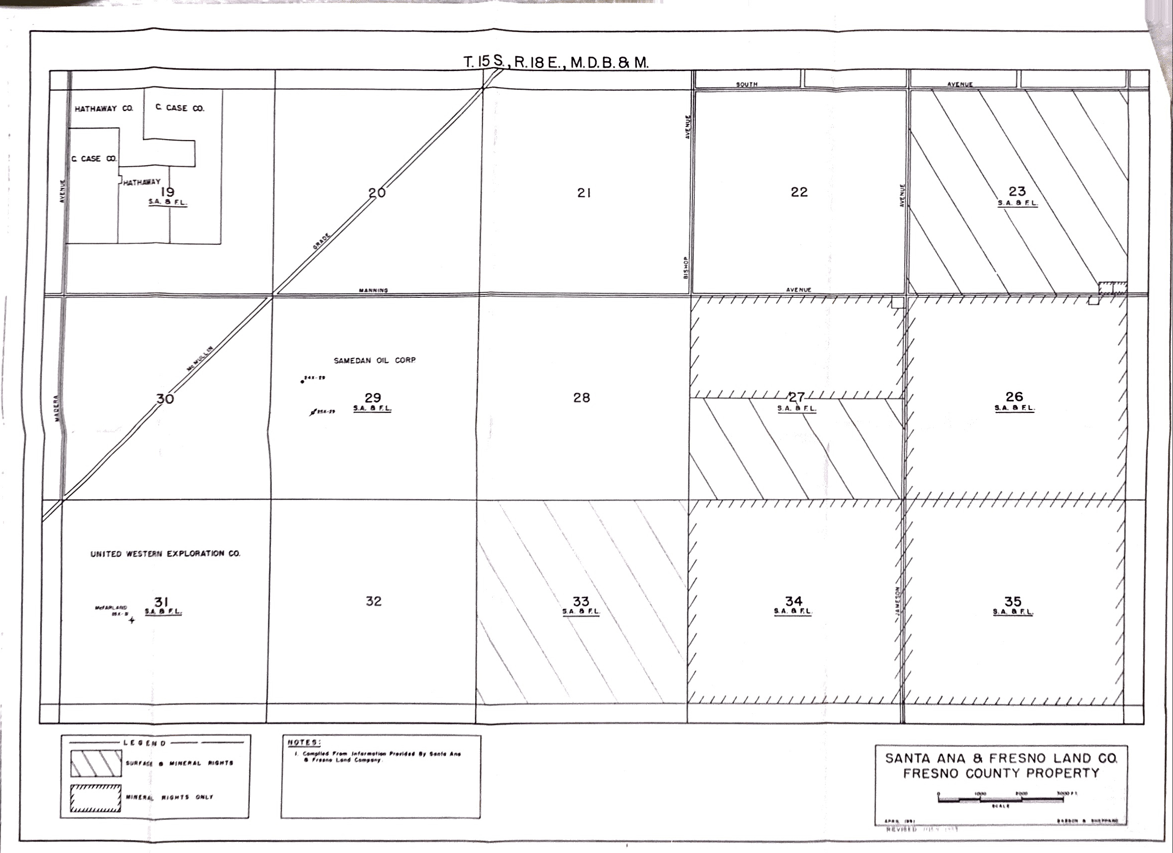
A survey township is divided into 36 sections, with a section being 1 mile square and holding 640 acres. Sections are numbered boustrophedonically within survey townships as follows: ( table is north up)
| 6 | 5 | 4 | 3 | 2 | 1 |
| 7 | 8 | 9 | 10 | 11 | 12 |
| 18 | 17 | 16 | 15 | 14 | 13 |
| 19 | 20 | 21 | 22 | 23 | 24 |
| 30 | 29 | 28 | 27 | 26 | 25 |
| 31 | 32 | 33 | 34 | 35 | 36 |
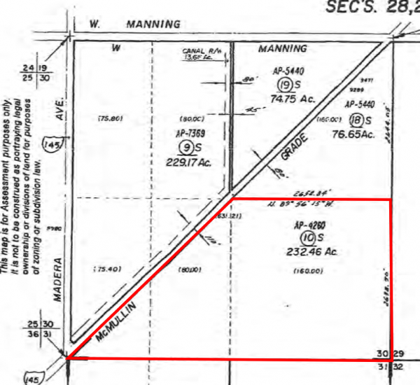
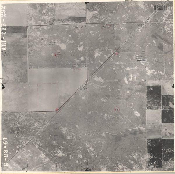
Our Section – 30 – south half, shaped as it is…
It might be fully described as SE 1/4 and SE 1/2, SW 1/4, Sec. 30, T.15S., R.18E. M.D.B. & M or in plain English, the SE quarter and SE half of the SW quarter of section 30 township 15 South and range 18 East – Mount Diablo Base as principal meridian.
The existence of section lines made property descriptions more straightforward. The establishment of east-west and north-south lines (“township” and “range lines”) meant that deeds could be written without regard to temporary terrain features such as trees, piles of rocks, fences, or the like. However, in our case the public roadway adds a complexity so we must rely on the record of survey filed in Book 22 of Records of survey at Page 73, Fresno County Records.
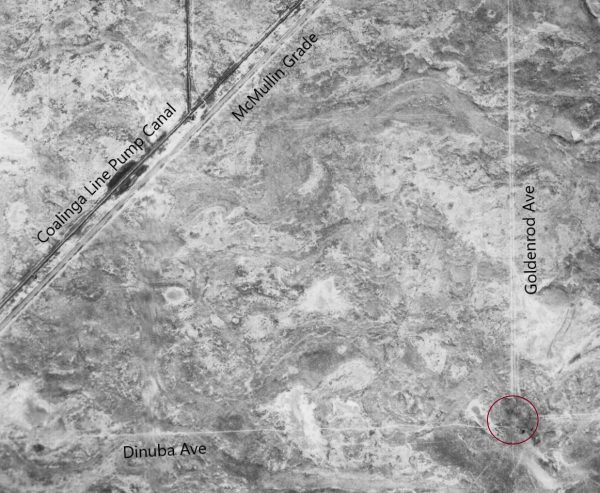
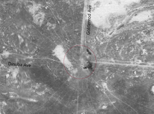
We are in the south half of Section 30 (subtracting ~ 80+ acres orphaned by S McMullin Grade, a diagonal bisecting our section)
You’ve heard this expression in story and song: “lower 40” or “back 40” — 40 acres was reference to a quarter-quarter section. There’s more in-depth reading on the PLSS design.
The Backstory Part
Historically these area lands in situ were of low value. The composition of the soil was alkali, predominately sandy loam, underlain with hardpan. There wasn’t a water supply so farming crops was unrealistic. Some areas in the vicinity were perceived to have petroleum reserves. Companies such as Getty Oil and Shell (circa 1923 – 1941) held oil leases. Few wells were able to extract oil in commercial quantities though, as this portion of the valley was at the northern extreme of the known Bakersfield oil resources.
Maintaining speculative hopes for oil, land conglomerates such as the Santa Ana Land Co. derived income primarily from cattle grazing leases. We leased acreage from Santa Ana. Our herd of steers fed on dry grass and hay supplement before trailing them to the [Noble] cattle feed yard for finishing. Years afterward this range where we ran cattle was acquired by Diego Lissi of Switzerland, and is renamed Terranova Ranch.
Land holder William H Noble, a wealthy individual from San Francisco, no doubt derived income from oil leases in his day but by the time we were on scene any wells were at their economic limit, if not fully abandoned. In 1962 we acquired land from Mr. Noble. Rik and Estee Strombotne purchased 230 acres within Section 30 with clear intent to develop their new parcel and to begin farming it.
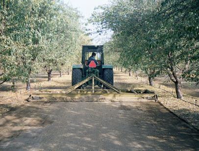
After the land was graded level and ripped, an irrigation well was drilled and gravity pipelines laid. Agricultural gypsum was applied and alfalfa planted. The chemistry of water, alfalfa crop and gypsum was the established method for reclaiming soil in the area. 1 We can be considered founders; one of the first in the area’s transformation and reclamation.
1 Wes Sprague – President 1968 – ____ of the Santa Ana and Fresno Land Company beginning from year 1909 owner of 9 Sections
Our earliest neighbors made similar efforts:
- Ken Peelman Jr. (leased) Sec. 19
- Jack Cardwell (leased) Sec. 29, 31, 33
- Klepper & Little (leased) Sec. 23 and south half of 27
- Coelho Brothers – Sec. 21
- Hartwig Brothers – north half Sec. 27
- Rau Brothers – Sec. 26, 35
- Britz Family – Sec. 32
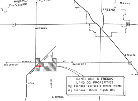
Our neighbors today: (click on a colored block to view)
The Naming Convention
Our property is also known as The Kerman Ranch because of its proximity to the city of that name but is actually closest to the unincorporated community of Helm, CA. We refer to the land as The Section 30. Technically not a Ranch by definition but from start beginning, when we cowboyed, it was open-range [ranch] land. Our farming venture transformed the Section 30 piece and made it the success that it has become.


